Материал: m013500e_x06
Feldbus-Koppler/-Controller • 61
Fieldbus Controller 750-806
3.2 Fieldbus Controller 750-806
This chapter includes:
3.2.1 |
Description...................................................................................... |
62 |
3.2.2 |
Hardware......................................................................................... |
63 |
3.2.2.1 |
View ......................................................................................... |
63 |
3.2.2.2 |
Device Supply .......................................................................... |
64 |
3.2.2.3 |
Fieldbus Connection................................................................. |
65 |
3.2.2.4 |
Display Elements ..................................................................... |
66 |
3.2.2.5 |
Configuration and Programming Interface .............................. |
67 |
3.2.2.6 |
Operating Mode Switch ........................................................... |
67 |
3.2.2.7 |
Hardware Address (MAC ID).................................................. |
68 |
3.2.2.8 |
Setting the Baud Rate............................................................... |
69 |
3.2.3 |
Operating System............................................................................ |
70 |
3.2.3.1 |
Start-up..................................................................................... |
70 |
3.2.3.2 |
PLC Cycle ................................................................................ |
70 |
3.2.4 |
Process Image ................................................................................. |
72 |
3.2.5 |
Data Exchange ................................................................................ |
73 |
3.2.5.1 |
Communication Interfaces ....................................................... |
74 |
3.2.5.2 |
Memory Areas.......................................................................... |
74 |
3.2.5.3 |
Addressing................................................................................ |
77 |
3.2.6 |
Programming the PFC with WAGO-I/O-PRO 32 .......................... |
81 |
3.2.6.1 |
WAGO-I/O-PRO 32 Library Elements.................................... |
81 |
3.2.6.2 |
IEC 61131-3 Program Transfer................................................ |
82 |
3.2.7 |
Special DeviceNet Features of the Controller................................. |
85 |
3.2.7.1 |
Connection via the UCMM port .............................................. |
85 |
3.2.7.2 |
Offline Connection Set............................................................. |
85 |
3.2.7.3 |
DeviceNet Shutdown ............................................................... |
85 |
3.2.7.4 |
Dynamic Assembly .................................................................. |
85 |
3.2.7.5 |
Change MAC ID by SW .......................................................... |
86 |
3.2.7.6 |
Heartbeat .................................................................................. |
86 |
3.2.7.7 |
Bit-Strobe ................................................................................. |
86 |
3.2.8 |
Configuration Software................................................................... |
87 |
3.2.9 |
Starting-up DeviceNet Fieldbus Nodes........................................... |
87 |
3.2.9.1 |
Connecting the PC and Fieldbus Node .................................... |
87 |
3.2.9.2 |
Setting the MAC ID and Baud Rate......................................... |
87 |
3.2.9.3 |
Configuration with Static and Dynamic Assembly.................. |
88 |
3.2.10 |
LED Display ................................................................................... |
99 |
3.2.10.2 |
Blink Code ............................................................................. |
101 |
3.2.11 |
Technical Data .............................................................................. |
103 |
WAGO-I/O-SYSTEM 750
DeviceNet

62 • Feldbus Coupler/Controller
Fieldbus Controller 750-806
3.2.1 Description
The programmable fieldbus Controller 750-806 (short: PFC) combines the DeviceNet functions of the fieldbus Coupler 750-306 with that of a programmable logic control (PLC).
The application program is created with WAGO-I/O-PRO 32 in accordance with IEC 61131-3.
All input signals of the sensors are grouped in the Controller.
According to the IEC 61131-3 programming, data processing occurs locally in the PFC. The link results created in this manner can be put out directly to the actuators or transmitted to the higher ranking control system via the bus.
The programmer has access to all fieldbus and I/O data.
In the initialization phase, the fieldbus Controller determines the physical structure of the node and creates a process image from this with all inputs and outputs. This could involve a mixed arrangement of analog (word by word data exchange) and digital (byte by byte data exchange) modules.
The local process image is subdivided into an input and output data area.
The data of the analog modules are mapped into the PDOs according to the order of their position downstream of the bus Coupler. The bits of the digital modules are compiled to form bytes and also mapped into PDOs. Should the number of digital I/Os exceed 8 bits, the Coupler automatically starts another byte.
In addition to the functions of the fieldbus Coupler, the fieldbus Controller supports the following DeviceNet functions:
•Create Connection via UCMM-Port
•Offline Connection Set
•DeviceNet Shutdown
•Dynamic assembly
•Change MAC ID by SW
•Heartbeat
•Bit-Strobe
WAGO-I/O-SYSTEM 750
DeviceNet
Feldbus-Koppler/-Controller • 63
Fieldbus Controller 750-806
3.2.2 Hardware
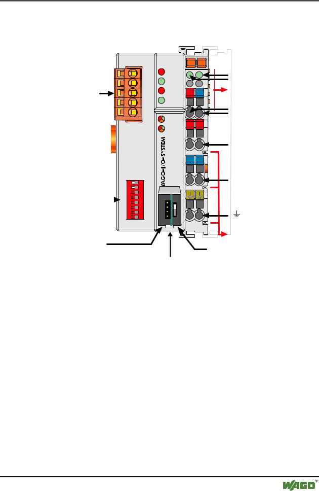
3.2.2.1 View
Fieldbus connection Series 231 (MCS)
1 |
ON |
2 |
|
DIP switch |
4 |
|
|
|
|
3 |
|
for MAC ID |
|
5 |
|
|
|
||
|
|
||
|
|
||
and baud rate |
7 |
|
|
|
|
6 |
|
|
|
8 |
|
|
|
|
|
|
|
|
|
|
|
|
|
Configuration and programming interface
DeviceNet |
01 |
02 |
|
OVERFL |
A |
C |
|
MS |
B |
||
RUN |
D |
||
|
|||
|
|
||
BUS OFF |
24V |
0V |
|
NS |
|
|
|
CONNECT |
|
|
|
I/O |
+ |
+ |
|
USR |
|||
|
|
Status voltage supply
-Power jumper contacts -System
Data contacts
Supply 24V 0V
Supply via power jumper contacts
24V
Ñ 
 Ñ
Ñ
806- |
0V |
|
750 |
||
|
Power jumper contacts
operating
mode switch
flap opened
Fig. 3-20: Fieldbus Controller 750-806 DeviceNet |
g080600e |
The fieldbus Controller is comprised of:
•Device supply with an internal system supply module as well as power jumper contacts for the field supply via assembled I/O modules
•Fieldbus interface with the bus connection
•DIP switch for baud rate and node ID
•Display elements (LEDs) for status display of the operation, the bus communication, the operating voltages as well as for fault messages and diagnosis
•Configuration and programming interface and operating mode switch
•Electronics for communication with the I/O modules (internal bus) and the fieldbus interface
WAGO-I/O-SYSTEM 750
DeviceNet
64 • Feldbus Coupler/Controller
Fieldbus Controller 750-806
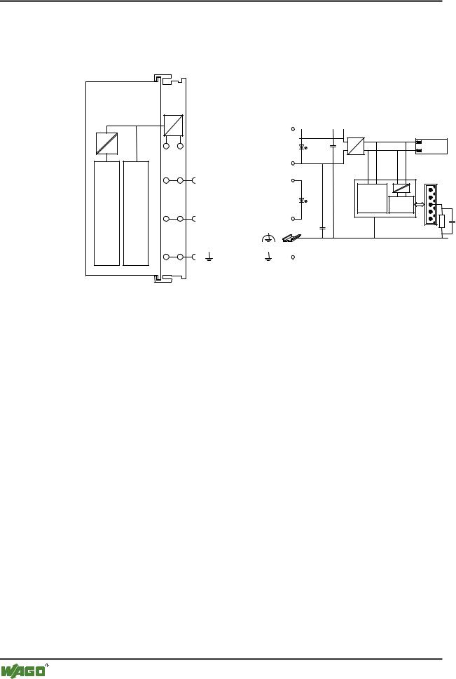
3.2.2.2 Device Supply
The voltage supply is fed in via the terminals with the CAGE CLAMP® connection. Device supply is intended for system supply and field side supply.
FIELDBUSINTERFACE |
ELECTRONICS |
|
|
24V |
|
|
1 |
5 |
|
DC |
Bus |
|
24V/0V |
10nF |
||
|
DC |
modules |
||
|
|
|
|
|
0V |
|
2 |
6 |
|
|
|
24V |
24V |
|
|
|
ELECTRONICS |
|
|
|
FIELDBUS |
|
|
|
INTERFACE |
|
3 |
7 |
1) |
2) |
|
0V |
0V |
|
10nF
1) 1M
4 |
8 |
2) 10nF/500V |
750-806
Fig. 3-21: Device supply |
g080601e |
The integrated internal system supply module generates the necessary voltage to supply the electronics and the connected I/O modules.
The fieldbus interface is supplied with electrically isolated voltage from the internal system supply module.
WAGO-I/O-SYSTEM 750
DeviceNet
Feldbus-Koppler/-Controller • 65
Fieldbus Controller 750-806
3.2.2.3 Fieldbus Connection
The scope of delivery includes the plug connector 231-305/010-000/050-000 from the WAGO MULTI CONNECTION SYSTEM. The connector has gold plated contacts and has the signal designations printed at it clamping units.
The connection diagram shows the table, the colours resulting in accordance with the DeviceNet specification and are identical to the conductor colours of the DeviceNet cables.
|
|
Pin |
Signal |
Code |
Description |
|
V+ |
5 |
V+ |
red |
11 ... 25 V |
|
|
|
|
|
|
Fieldbus |
CAN_High 4 |
CAN_H |
white |
CAN Signal High |
|
connection |
|
3 |
Shield |
|
Shield connection |
Series 231 |
drain |
|
|||
|
|
|
|
|
|
(MCS) |
CAN_Low |
2 |
CAN_L |
blue |
CAN Signal Low |
|
|
||||
|
V- |
1 |
V- |
black |
0 V |
|
|
||||
Fig. 3-22: Fieldbus connection, MCS |
|
|
|
g012500e |
|
For the connection of small conductor cross sections, we recommend to insert an insulation stop from series 231-670 (white), 231-671 (light grey) or 231672 (dark grey) due to the low kink resistance. This insulation stop prevents a conductor from kinking when it hits the conductor contact point, and as such, the conductor insulation from being also entered into and clamped in the connection point. Connector marking, housing components, test connectors including cables and heater connectors for cable extensions, are available.
The connection point is lowered in such a way that after a connector is inserted, installation in an 80 mm high switchbox is possible.
The electrical isolation between the fieldbus system and the electronics is made via the DC/DC converter and the optocoupler in the fieldbus.
WAGO-I/O-SYSTEM 750
DeviceNet