Материал: m013500e_x06
Fieldbus Coupler/Controller • 51
Fieldbus Coupler 750-306
3.1.6 Configuration Software
To enable a connection between the PLC and the fieldbus devices, the interface modules have to be configured with the individual station data.
To this effect, the scope of delivery of WAGO-I/O-SYSTEM 758 includes the WAGO NETCON software intended for design and configuration, start-up and diagnosis.
Further configuration software of different manufacturers include, for instance, RSNetWorx.
3.1.7 Starting up DeviceNet Fieldbus Nodes
This chapter shows the step-by-step procedure for starting up a
WAGO DeviceNet fieldbus node.
Attention
This description is given as an example and is limited to the execution of a local start-up of an individual DeviceNet fieldbus node.
The procedure contains the following steps:
1.Connecting the PC and fieldbus node
2.Setting the MAC ID and baud rate
3.Configuration with static Assembly
3.1.7.1Connecting the PC and Fieldbus Node
1.Connect the fitted DeviceNet fieldbus node to the DeviceNet fieldbus PCB in your PC via a fieldbus cable.
The 24 V field bus supply is fed by an external fieldbus network power supply over the connections V+, V- of the 5-pin fieldbus connector (MCS Series 231).
2.Start your PC.
3.1.7.2Setting the MAC ID and Baud Rate
1.Use the DIP switches 1...6 to set the desired node address (MAC ID). The binary significance of the individual DIP switches increases according to the switch number.
1 2 3 |
ON |
DIP switch |
Value |
|
1 |
20 |
|||
4 |
|
2 |
21 |
|
5 |
|
3 |
2 |
|
6 |
|
2 |
||
|
|
|
||
|
|
|
|
|
7 8 |
g012443x |
4 |
23 |
|
|
5 |
24 |
||
Fig. 3-10: Example: Setting the |
6 |
25 |
||
MAC ID 4 (DIP 3 = ON). |
||||
WAGO-I/O-SYSTEM 750
DeviceNet
52 • Fieldbus Coupler/Controller
Fieldbus Coupler 750-306
2. DIP switches 7 and 8 are used to set the desired baud rate.
1 |
1 2 |
ON |
|
2 |
|||
|
|
33 


44 


 ON
ON
55 


66 


7 |
7 |
|
8 |
8 |
g012541x
Fig. 3-11: Example: Setting the baud rate 250 kBaud (DIP 7 = ON) of the station with MAC ID 1.
Baud rate |
DIP7 |
DIP8 |
125 kBaud*) |
OFF |
OFF |
250 kBaud |
ON |
OFF |
|
|
|
500 kBaud |
OFF |
ON |
|
|
|
not allowed |
ON |
ON |
*) Presetting |
|
|
3.Then switch on the Coupler supply voltage.
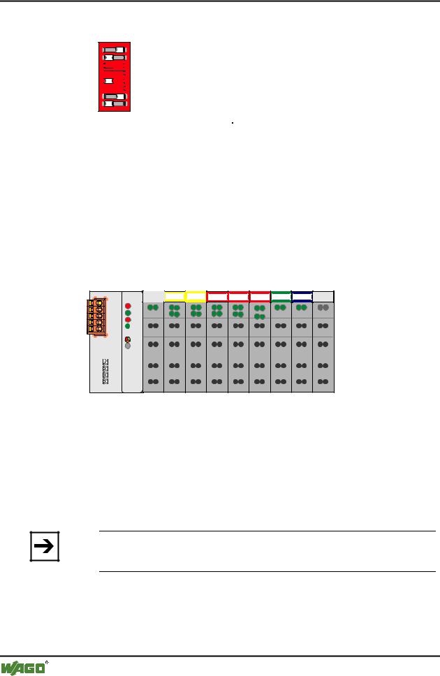
3.1.7.3Configuration with Static Assembly
In this example, the software WAGO NETCON is used for the configuration.
The node in the example consists of the following I/O modules:
1 |
2 |
3 |
4 |
5 |
6 |
7 |
8 |
DI DI |
DI DI |
DODO DODO DODO AI AI |
AO AO |
|
|
750-306 |
|
|
|
|
|
|
|
|
|
|
|
|
|
|
|
|
|
|
|
|
|
|
|
|
|
|
|
|
|
|
|
|
|
|
|
|
|
|
|
|
|
|
|
|
|
|
|
|
|
|
|
|
|
|
|
|
|
|
|
|
|
|
|
|
|
|
|
|
|
|
|
|
|
|
|
|
|
|
|
|
|
|
|||
|
|
|
|
|
|
|
|
|
|
|
|
|
|
516 |
|
|
|
|
|||
|
|
|
|
|
|
|
|
|
||
402 |
402 |
516 |
516 |
467 |
550 |
600 |
||||
Fig. 3-12: Example for a fieldbus node |
g012552x |
1.Starting Software and EDS file load
1.Start the configuration software WAGO NETCON.
2.Load an EDS file for the fieldbus Coupler in WAGO NETCON, i. e. "4.EDS".
For this click on "File/ Copy EDS" and choose the EDS-file to load.
Note
You can download the EDS files for the fieldbus Coupler from the Internet under: www.wago.com.
Upon downloading the EDS file into WAGO NETCON, you can create a new project and start configuring your network.
WAGO-I/O-SYSTEM 750
DeviceNet
Fieldbus Coupler/Controller • 53
Fieldbus Coupler 750-306
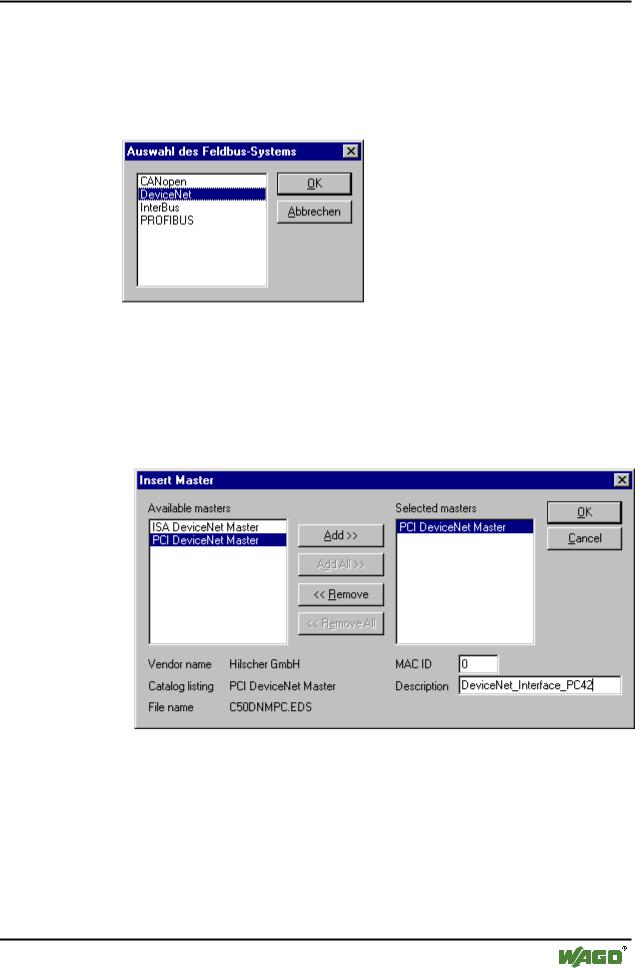
2. Create a new project
1.Enter the "File" menu and click on menu point "New".
2.Select "DeviceNet" as the fieldbus system and confirm your selection by clicking on the "OK" button.
Fig. 3-13: Select fieldbus |
p112501d |
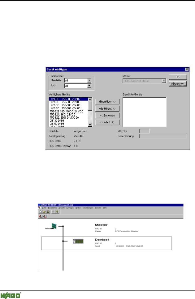
3.Enter Master
1.Enter a fieldbus master on the surface by clicking on the „Master“ menu point in the "Insert" menu.
A dialog window opens in which you can select the DeviceNet fieldbus card in your PC.
Fig. 3-14: Select the DeviceNet fieldbus PCB / Insert Master |
p1x2602d |
2.For the DeviceNet Master interface card, click in the left-hand selection window on the corresponding entry to mark it.
3.Take the Master into the right-hand window by clicking on the "Add" button and confirm by clicking on the "OK" button.
Now the fieldbus master is shown on the surface as a graphic.
WAGO-I/O-SYSTEM 750
DeviceNet
54 • Fieldbus Coupler/Controller
Fieldbus Coupler 750-306
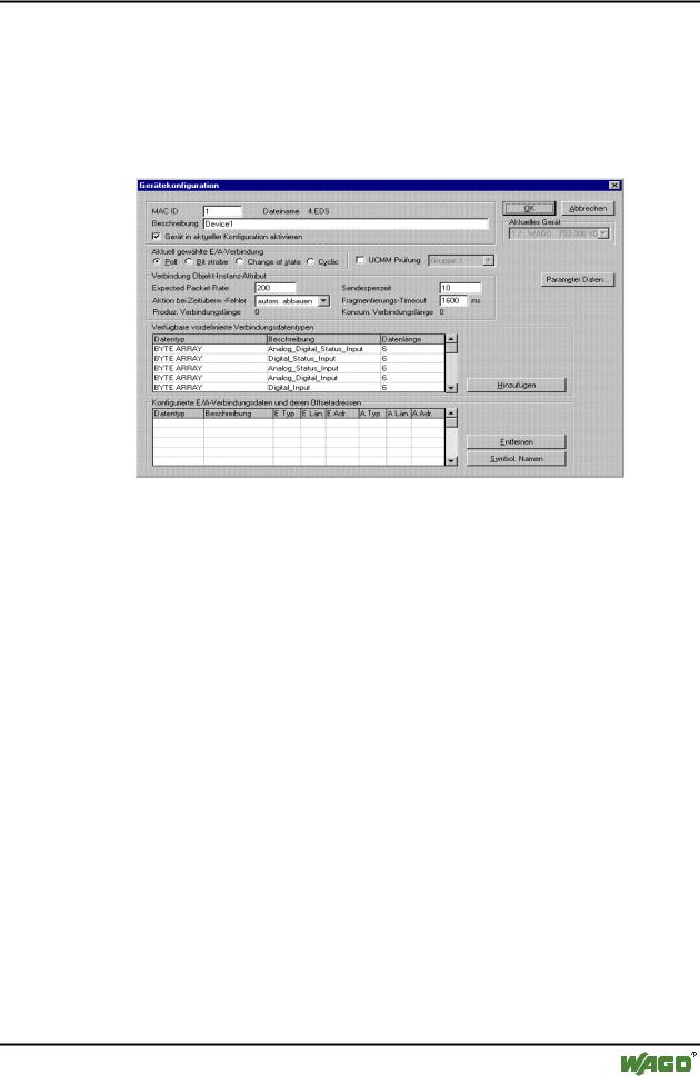
4.Add a slave
1.Enter a fieldbus slave on the surface by clicking on the “Device” menu point in the "Insert" menu.
The mouse pointer changes to the letter D with an arrow.
2.Move this mouse pointer to the graphic display of the fieldbus, then click on the left-hand mouse key.
A dialog window opens permitting you to select a DeviceNet device.
Fig. 3-15: |
Insert slave |
p012501d |
3.For the fieldbus Coupler 750-306 click in the left-hand selection window on the corresponding entry to mark it.
4.Take this into the right-hand window by clicking on the "Add" button and confirm by clicking on the "OK" button.
The configuration is displayed on the surface as a graphic.
Fig. 3-16: Configuration |
p012502d |
WAGO-I/O-SYSTEM 750
DeviceNet
Fieldbus Coupler/Controller • 55
Fieldbus Coupler 750-306
5.Device configuration
1.To configure the device, click on its graphic to mark it, then click on the menu point “Device configuration” in the "Settings" menu.
A dialog window opens permitting you to proceed with the desired settings.
Fig. 3-17: Device Configuration |
p112505d |
6.Load configuration
1.To load the set configuration in the interface card, click on the master’s graphic to mark it, then click on the “Download” menu point in the "Online" menu.
WAGO-I/O-SYSTEM 750
DeviceNet