Материал: m013500e_x06
46 • Fieldbus Coupler/Controller
Fieldbus Coupler 750-306
3.1.4 Process Image
After powering up, the Coupler recognizes all I/O modules plugged into the node which supply or wait for data (data width/bit width > 0). In the nodes, analog and digital I/O modules can be mixed.
The Coupler produces an internal process image from the data width and the type of I/O module as well as the position of the I/O modules in the node. It is divided into an input and an output data area.
The data of the digital I/O modules is bit orientated, i.e. the data exchange is made bit for bit. The analog I/O modules are all byte orientated I/O modules, i.e. modules where the data exchange is made byte for byte. These I/O modules include, for example, the counter modules, I/O modules for angle and path measurement as well as the communication modules.
Note
For the number of input and output bits or bytes of the individual I/O modules, please refer to the corresponding I/O module description.
The data of the I/O modules is separated for the local input and output process image in the sequence of their position after the Coupler in the individual process image.
In the respective I/O area, analog modules are mapped first, then all digital modules, even if the order of the connected analog and digital modules does not comply with this order. The digital channels are grouped, each of these groups having a data width of 1 byte. Should the number of digital I/Os exceed 8 bits, the Coupler automatically starts another byte.
Note
A process image restructuring may result if a node is changed or extended. In this case, the process data addresses also change in comparison with earlier ones. In the event of adding a module, take the process data of all previous modules into account.
WAGO-I/O-SYSTEM 750
DeviceNet

Fieldbus Coupler/Controller • 47
Fieldbus Coupler 750-306
3.1.5 Data Exchange
With DeviceNet, the transmission and exchange of data is made using objects.
For a network access on the single objects of the Coupler, it is necessary to create a connection between the desired participants and to allocate connection objects.
For an easy and quick set-up of a connection, the DeviceNet fieldbus Coupler 750-306 uses the "Predefined Master/Slave Connection Set", which contains 4 pre-defined connections. For the access on the Coupler the connections only need to be allocated. The "Predefined Master/Slave Connection Set" confines itself to pure Master/Slave relationships.
The DeviceNet fieldbus Coupler 750-306 can only communicate via its assigned client and it is a so-called "Group 2 Only Server". The Group 2 Only Server communicating is only possible via the Group 2 Only Unconnected Explicit Message Port. These slaves exclusively receive messages defined in message group 2.
The object configuration for the data transmission is defined by an Assembly Object. The Assembly Object can be used to group data (e.g. I/O data) into blocks (mapping) and send this data via one single communication connection. This mapping results in a reduced number of accesses to the network.
A differentiation is made between "Input-Assemblies" and "OutputAssemblies".
An Input-Assembly reads in data from the application via the network or produces data on the network respectively.
An Output-Assembly writes data to the application or consumes data from the network respectively.
Various Assembly instances are permanently programmed (static assembly) in the fieldbus Coupler.
Further information
The Assembly instances for the static assembly are described in chapter 5.5.1.1 "Assembly Instance".
WAGO-I/O-SYSTEM 750
DeviceNet
48 • Fieldbus Coupler/Controller
Fieldbus Coupler 750-306
3.1.5.1 Communication Interfaces
For a data exchange, the DeviceNet fieldbus Coupler is equipped with two interfaces:
•the interface to fieldbus (-master) and
•the interface to the bus modules.
Data exchange takes place between the fieldbus master and the bus modules. Access from the fieldbus side is fieldbus specific.
3.1.5.2 Memory Areas
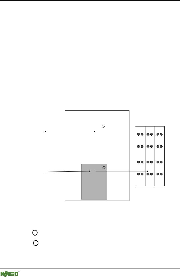
The Coupler uses a memory space of 256 words (word 0 ... 255) for the physical input and output data.
The division of the memory spaces is identical with all WAGO fieldbus Couplers.
fieldbus coupler
fieldbus |
memory area |
|
|
||||||
for input data |
|
|
|||||||
|
|
|
|
word 0 |
|
|
|
||
|
|
|
|
1 |
|
|
|
||
|
|
|
|
|
|
|
|
|
|
|
|
|
|
|
input |
|
|
|
|
|
|
|
|
modules |
|
|
|
||
|
|
|
|
word 255 |
|
|
|
||
|
|
|
|
memory area |
|
|
|||
|
|
|
|
for output data |
|
|
|||
|
|
|
|
word 0 |
|
|
|||
|
|
|
|
2 |
|
|
|
||
|
|
|
|
|
output |
|
|
||
|
|
|
|
modules |
|
|
|||
|
|
|
|
|
|
|
|
|
|
I/O modules
I O
word 255 |
|
Fig. 3-9: Memory areas and data exchange for a fieldbus Coupler |
g012433e |
The Coupler process image contains the physical data of the bus modules in a storage area for input data and in a storage area for output data (word 0 ... 255 each).
1The input module data can be read from the fieldbus side.
2In the same manner, writing to the output modules is possible from the fieldbus side.
WAGO-I/O-SYSTEM 750
DeviceNet
Fieldbus Coupler/Controller • 49
Fieldbus Coupler 750-306
3.1.5.3 Addressing
3.1.5.3.1 Fieldbus Specific
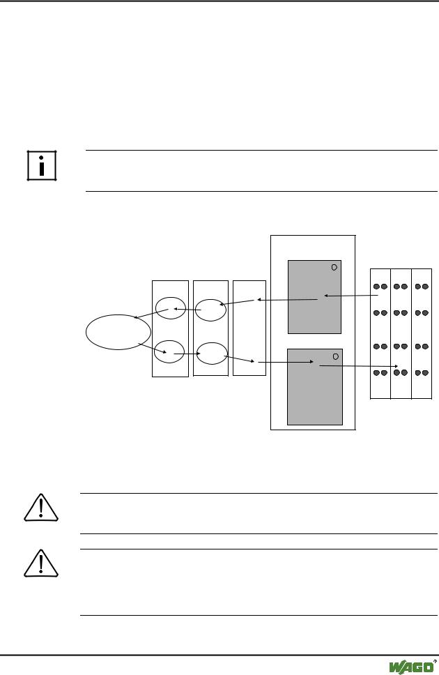
Once the supply voltage is applied, the Assembly Object maps data from the process image. As soon as a connection is established, a DeviceNet-Master (Scanner) can address and access the data by "Class", "Instance" and "Attribute".
Data mapping depends on the selected Assembly Instance of the static Assembly.
Further information
The Assembly Instances of the static Assembly are described in chapter 5.5.1.1 "Assembly Instance".
fieldbus master
Fieldbus coupler
memory area for input data
word 0 |
1 |
I/O modules |
Connection |
Assembly |
Application |
input |
|
modules |
|
|||
Object |
Object |
Object |
|
|
|
|
|||
Producer |
Input- |
|
|
|
|
|
|
|
|
|
Assemly |
|
|
|
|
|
|
word 255 |
|
|
|
|
memory area |
|
Consumer |
Output- |
|
for output data |
|
|
|
word 0 |
|
|
|
Assemly |
|
2 |
|
|
|
|
||
|
|
|
output |
|
|
|
|
modules |
|
I O
word 255
Fig. 3-1: Fieldbus specific data exchange for a DeviceNet fieldbus Coupler |
g012531e |
Note
For the number of input and output bits or bytes of the individual I/O modules, please refer to the corresponding I/O module description.
Note
A process image restructuring may result if a node is changed or extended. In this case the process data addresses also change in comparison with earlier ones. In the event of adding a module, take the process data of all previous modules into account.
WAGO-I/O-SYSTEM 750
DeviceNet

50 • Fieldbus Coupler/Controller
Fieldbus Coupler 750-306
Example for static assembly (default assembly):
The default assembly is: |
|
Output1 |
(I/O Assembly Instance 1) |
Input1 |
(I/O Assembly Instance 4) |
In this example, the fieldbus node arrangement looks like this:
1)1 fieldbus coupler DeviceNet (750-306),
2)1 digital 4-channel input module (i. e. 750-402),
3)1 digital 4- channel output module (i. e. 750-504),
4)1 analog 2- channel output module with 2 bytes per channel (i. e. 750-552),
5)1 analog 2- channel input module with 2 bytes per channel (i. e. 750-456),
6)1 End module (750-600).
Input process image:
Default process data, input image (Assembly Class, Instance 4)
Byte |
.7 |
.6 |
.5 |
.4 |
.3 |
.2 |
.1 |
.0 |
0 |
|
|
|
low byte channel 1 |
|
|
|
|
1 |
|
|
|
high byte channel 1 |
|
|
|
|
2 |
|
|
|
low byte channel 2 |
|
|
|
|
3 |
|
|
|
high byte channel 2 |
|
|
|
|
4 |
|
not used |
|
DI041) |
DI031) |
DI021) |
DI011) |
|
5 |
DS08 2) |
DS07 2) |
DS06 2) |
DS05 2) |
DS04 2) |
DS03 2) |
DS02 2) |
DS01 2) |
1)DI = Digital Input
2)DS = Diagnostic Status
Output process image:
Default process data, output image (Assembly Class, Instance 1)
Byte |
.7 |
.6 |
|
.5 |
.4 |
.3 |
.2 |
.1 |
.0 |
0 |
|
|
|
|
low byte channel 1 |
|
|
|
|
1 |
|
|
|
|
high byte channel 1 |
|
|
|
|
2 |
|
|
|
|
low byte channel 2 |
|
|
|
|
3 |
|
|
|
|
high byte channel 2 |
|
|
|
|
4 |
|
|
not used |
|
DO041) |
DO031) |
DO021) |
DO011) |
|
1) DO = Digital Output
WAGO-I/O-SYSTEM 750
DeviceNet