Материал: m013500e_x06
36• The WAGO-I/O-SYSTEM 750
Shielding (screening)
2.8 Shielding (screening)
2.8.1 General
The shielding of the data and signal conductors reduces the electromagnetic influences thereby increasing the signal quality. Measurement errors, data transmission errors and even disturbances caused by overvoltage can thus be avoided.
Attention
Constant shielding is absolutely required in order to ensure the technical specifications in terms of the measurement accuracy.
The data and signal conductors should be laid separately from all highvoltage cables.
The cable shield is to be laid over a large-scale surface onto the earth potential. With this, incoming disturbances can be easily diverted.
The shielding should be placed over the entrance of the cabinet or housing in order to already repel disturbances at the entrance.
2.8.2 Bus Conductors
The shielding of the bus conductor is described in the relevant assembly guideline of the bus system.
2.8.3 Signal Conductors
The bus terminals for analogue signals as well as some interface bus terminals possess connection terminals for the shield.
Note
Improved shielding can be achieved if the shield is previously placed over a large-scale surface. For this, we recommend the use of the WAGO shield connecting system for example.
This is particularly recommendable for systems with large-scale expansions where it cannot be ruled out that differential currents are flowing or high pulse currents, i. e. activated by atmospheric discharge, may appear.
WAGO-I/O-SYSTEM 750
DeviceNet
The WAGO-I/O-SYSTEM 750 • 37
Assembly Guidelines / Norms
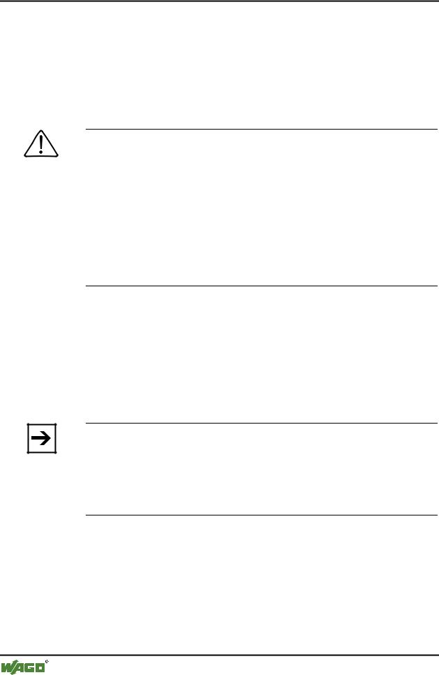
2.8.4 WAGO Shield (Screen) Connecting System
The WAGO shield connecting system is comprised of shield terminal frames, busbars and diverse assembly feet in order to realize a multitude of constructions. Please see catalogue W3 volume 3 chapter 7.
Fig. 2-25: WAGO Shield (Screen) Connecting System
p0xxx08x, p0xxx09x, and p0xxx10x
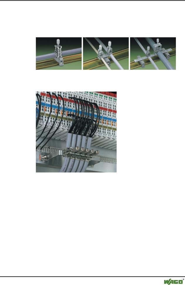
Fig. 2-26: Application of the WAGO Shield (Screen) Connecting System |
p0xxx11x |
2.9 Assembly Guidelines / Norms
DIN 60204, |
Electrical equipping of machines |
DIN EN 50178 |
Equipping of high-voltage systems with electronic |
|
components (replacement for VDE 0160) |
EN 60439 |
Low voltage – switch box combinations |
WAGO-I/O-SYSTEM 750
DeviceNet

38 • Fieldbus Coupler/Controller
Fieldbus Coupler 750-306
3 Fieldbus Coupler/Controller
3.1 Fieldbus Coupler 750-306
This chapter includes:
3.1.1 |
Description ...................................................................................... |
39 |
3.1.2 |
Hardware......................................................................................... |
40 |
3.1.2.1 |
View ......................................................................................... |
40 |
3.1.2.2 |
Device Supply .......................................................................... |
41 |
3.1.2.3 |
Fieldbus Connection................................................................. |
42 |
3.1.2.4 |
Display Elements...................................................................... |
43 |
3.1.2.5 |
Configuration Interface ............................................................ |
44 |
3.1.2.6 |
Hardware Address (MAC ID) .................................................. |
44 |
3.1.2.7 |
Setting the Baud Rate............................................................... |
45 |
3.1.3 |
Operating System............................................................................ |
45 |
3.1.4 |
Process Image ................................................................................. |
46 |
3.1.5 |
Data Exchange ................................................................................ |
47 |
3.1.5.1 |
Communication Interfaces ....................................................... |
48 |
3.1.5.2 |
Memory Areas.......................................................................... |
48 |
3.1.5.3 |
Addressing................................................................................ |
49 |
3.1.6 |
Configuration Software................................................................... |
51 |
3.1.7 |
Starting up DeviceNet Fieldbus Nodes........................................... |
51 |
3.1.7.1 |
Connecting the PC and Fieldbus Node .................................... |
51 |
3.1.7.2 |
Setting the MAC ID and Baud Rate......................................... |
51 |
3.1.7.3 |
Configuration with Static Assembly ........................................ |
52 |
3.1.8 |
LED Display ................................................................................... |
56 |
3.1.8.1 |
Node Status .............................................................................. |
57 |
3.1.8.2 |
Blink Code................................................................................ |
58 |
3.1.8.3 |
Fault Message via the Blink Code of the I/O LED .................. |
58 |
3.1.8.4 |
Supply Voltage Status .............................................................. |
59 |
3.1.9 |
Technical Data ................................................................................ |
60 |
WAGO-I/O-SYSTEM 750
DeviceNet

Fieldbus Coupler/Controller • 39
Fieldbus Coupler 750-306
3.1.1 Description
The fieldbus Coupler 750-306 displays the peripheral data of all I/O modules in the WAGO-I/O-SYSTEM 750 on DeviceNet Feldbus. The data is transmitted with objects.
The bus Coupler determines the physical structure of the node and creates a process image from this with all inputs and outputs. This could involve a mixed arrangement of analog (word by word data exchange) and digital (byte by byte data exchange) modules.
The local process image is subdivided into an input and output data area. The process data can be read in via the DeviceNet bus and further processed in a control system. The process output data is sent via the DeviceNet bus.
The data of the analog modules are mapped into the automatical created process image according to the order of their position downstream of the bus Coupler. The bits of the digital modules are compiled to form bytes and also mapped into the process image attached to the data of the analog modules. Should the number of digital I/Os exceed 8 bits, the Coupler automatically starts another byte.
The fieldbus Coupler supports the DeviceNet function Bit-Strobe, whereby the function is insofar restricted, that only the status byte will be delivered.
WAGO-I/O-SYSTEM 750
DeviceNet
40 • Fieldbus Coupler/Controller
Fieldbus Coupler 750-306
3.1.2 Hardware
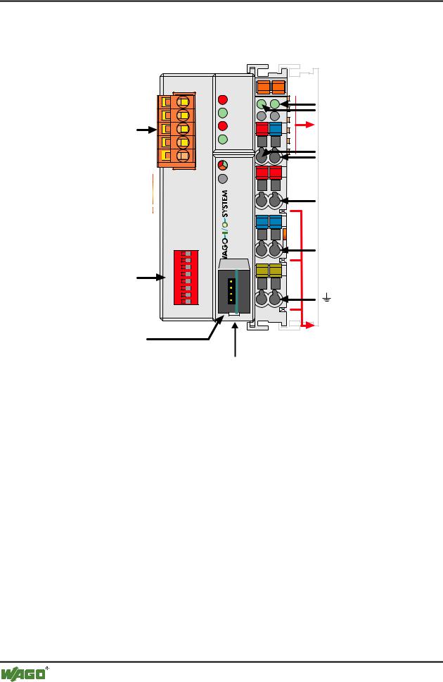
3.1.2.1 View
Fieldbus connection Series 231 (MCS)
|
|
|
|
|
|
|
|
|
|
|
|
|
|
|
|
|
|
|
|
|
|
|
|
|
|
|
|
|
|
|
|
|
|
|
|
|
|
|
|
|
|
|
|
|
|
|
|
|
|
|
|
|
|
|
|
|
|
|
|
1 |
|
ON |
|||
|
|||||
2 |
|
||||
|
|
||||
DIP switch |
4 |
|
|
3 |
|
for MAC ID |
5 |
|
|
||
|
||
|
||
and baud rate |
7 |
|
|
6 |
|
|
8 |
|
|
|
|
|
|
|
|
|
Configuration interface
|
|
|
Status |
|
DeviceNet |
01 |
02 |
voltage supply |
|
-Power jumper |
||||
OVERFL |
|
|
||
A |
C |
contacts |
||
MS |
B |
-System |
||
RUN |
D |
|||
|
|
|
||
BUS OFF |
24V |
0V |
Data contacts |
|
NS |
|
|
Supply |
|
CONNECT |
|
|
||
|
|
|
24V |
|
I/O |
|
|
0V |
|
+ |
+ |
|
||
|
Supply via |
|||
|
|
|
power jumper |
|
|
|
|
contacts |
|
|
|
|
24V |
|
|
Ñ |
Ñ |
|
|
-306 |
|
|
0V |
|
750 |
|
|
||
|
|
|
||
|
PE |
PE |
|
|
|
|
|
Power jumper |
|
|
|
|
contacts |
flap opened
Fig. 3-1: Fieldbus Coupler 750-306 DeviceNet |
g030600e |
The fieldbus Coupler comprises of:
•Supply module with Internal system supply module for the system supply as well as power jumper contacts for the field supply via I/O module assemblies.
•Fieldbus interface with the bus connection
•DIP switch for baud rate and MAC ID
•Display elements (LED's) for status display of the operation, the bus communication, the operating voltages as well as for fault messages and diagnosis
•Configuration interface
•Electronics for communication with the I/O modules (internal bus) and the fieldbus interface
WAGO-I/O-SYSTEM 750
DeviceNet