Материал: m013500e_x06
Fieldbus Coupler/Controller • 41
Fieldbus Coupler 750-306
3.1.2.2 Device Supply
The supply is made via terminal blocks with CAGE CLAMP® connection. The device supply is intended both for the system and the field units.
|
|
|
|
|
|
|
|
|
|
|
|
|
|
|
FIELDBUSINTERFACE |
ELECTRONICS |
|
|
|
|
|
|
|
|
|
|
|
|
|
|
|
24V |
|
|
1 |
5 |
|
DC |
Bus |
|
24V/0V |
10nF |
||
|
DC |
modules |
||
|
|
|
|
|
|
0V |
|
2 |
6 |
|
|
|
24V |
24V |
|
|
|
ELECTRONICS |
|
|
|
FIELDBUS |
|
|
|
INTERFACE |
|
3 |
7 |
1) |
2) |
|
0V |
0V |
|
10nF
1) 1M
4 |
8 |
2) 10nF/500V |
750-306
Fig. 3-2: Device supply |
g030601e |
The integrated internal system supply module generates the necessary voltage to supply the electronics and the connected I/O modules.
The fieldbus interface is supplied with electrically isolated voltage from the internal system supply module.
WAGO-I/O-SYSTEM 750
DeviceNet
42 • Fieldbus Coupler/Controller
Fieldbus Coupler 750-306
3.1.2.3 Fieldbus Connection
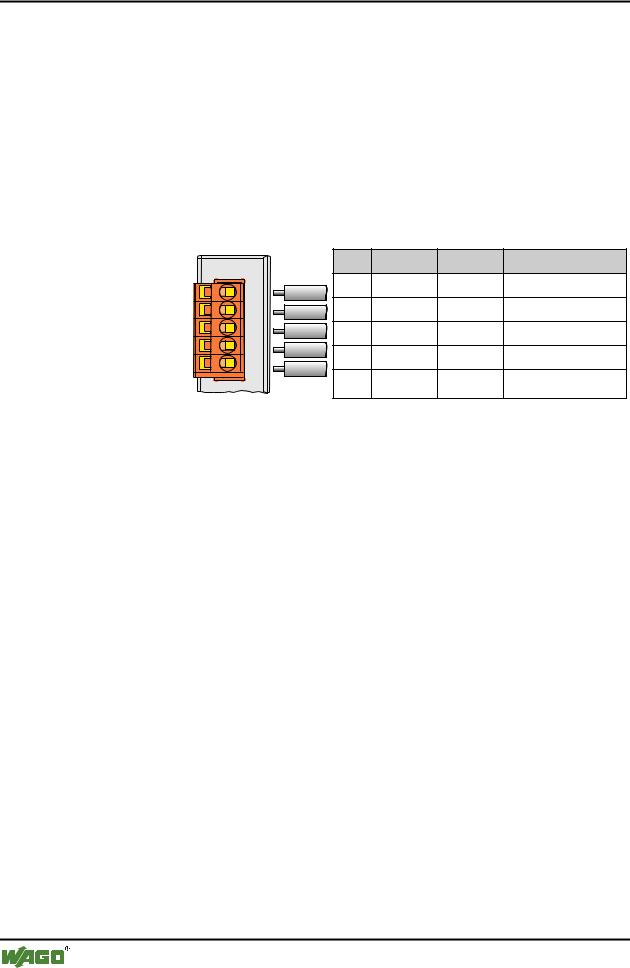
For the field bus connection, the DeviceNet interface is equipped with a 5 pole header, its counter-piece being a plug connector (Open Style Connector).
The scope of delivery includes the plug connector 231-305/010-000/050-000 from the WAGO MULTI CONNECTION SYSTEM. The connector has gold plated contacts and has the signal designations printed at its clamping units.
The table shows the connection diagram, the colours resulting in accordance with the DeviceNet specification and are identical to the conductor colours of the DeviceNet cables.
|
|
Pin |
Signal |
Code |
Description |
|
V+ |
5 |
V+ |
red |
11 ... 25 V |
|
|
|
|
|
|
Fieldbus |
CAN_High 4 |
CAN_H |
white |
CAN Signal High |
|
connection |
|
3 |
Shield |
|
Shield connection |
Series 231 |
drain |
|
|||
(MCS) |
CAN_Low |
2 |
CAN_L |
blue |
CAN Signal Low |
|
|
||||
|
V- |
1 |
V- |
black |
0 V |
|
|
||||
Fig. 3-3: Fieldbus connection, MCS |
|
|
|
g012500e |
|
For the connection of small conductor cross sections, we recommend to insert an insulation stop from series 231-670 (white), 231-671 (light grey) or 231672 (dark grey) due to the low kink resistance. This insulation stop prevents a conductor from kinking when it hits the conductor contact point, and as such the conductor insulation from being also entered into and clamped in the connection point. Connector marking, housing components, test connectors including cables and header connectors for cable extensions are available.
The connection point is lowered in such a way that after a connector is inserted, installation in an 80 mm high switchbox is possible.
The electrical isolation between the fieldbus system and the electronics is made via the DC/DC converter and the optoCoupler in the fieldbus.
WAGO-I/O-SYSTEM 750
DeviceNet
Fieldbus Coupler/Controller • 43
Fieldbus Coupler 750-306
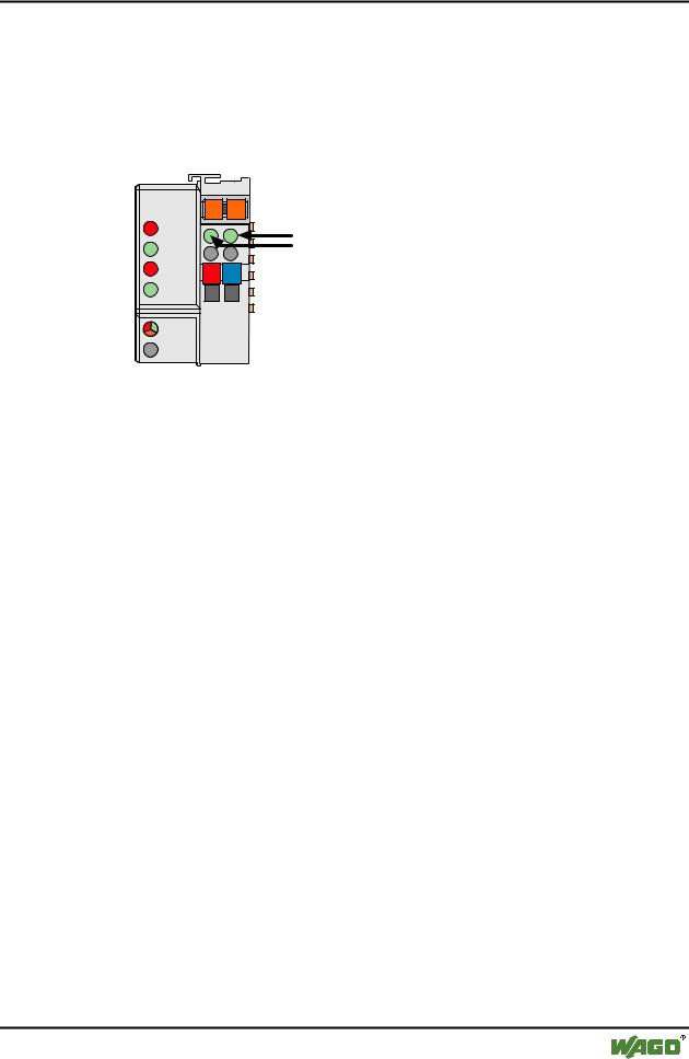
3.1.2.4 Display Elements
The operating condition of the fieldbus Coupler or node is signalled via light diodes (LED).
Four LEDs, specific for DeviceNet (OVERFL, RUN, BUSOFF, CONNECT), indicate the module status (MS) and the network status (NS).
DeviceNet |
01 |
02 |
|
OVERFL |
A |
C |
C |
MS |
B |
A |
|
RUN |
|
||
|
D |
||
|
|
|
|
BUS OFF |
24V |
0V |
|
NS |
|
|
|
CONNECT |
|
|
|
I/O |
|
|
|
Fig. 3-4: Display elements 750-306 |
g030602x |
|||
|
|
|
|
|
|
LED |
Color |
Meaning |
|
|
OVERFL |
red |
Errors or faults at the fieldbus Coupler. |
|
|
|
|
|
|
|
RUN |
green |
Fieldbus Coupler is ready for operation. |
|
|
|
|
|
|
|
BUS OFF |
red |
Error or malfunction at network |
|
|
|
|
|
|
|
CONNECT |
green |
Fieldbus Coupler is ready for network communication. |
|
|
|
|
|
|
|
I/O |
red/ |
The ‚I/O‘-LED indicates the operation of the node and signals faults |
|
|
|
green/ |
encountered. |
|
|
|
orange |
|
|
|
|
|
|
|
|
A |
green |
Status of the operating voltage system |
|
|
|
|
|
|
|
C |
green |
Status of the operating voltage – power jumper contacts |
|
|
|
|
|
|
WAGO-I/O-SYSTEM 750
DeviceNet
44 • Fieldbus Coupler/Controller
Fieldbus Coupler 750-306
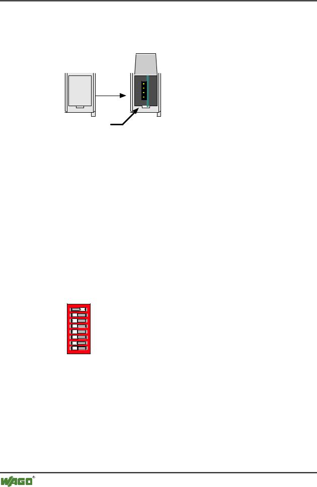
3.1.2.5 Configuration Interface
The configuration interface used for the communication with WAGO-I/O-CHECK or for firmware transfer is located behind the cover flap.
open flap
Configuration interface
Fig. 3-5: Configuration interface g01xx06e
The communication cable (750-920) is connected to the 4-pole header.
3.1.2.6 Hardware Address (MAC ID)
The DIP switch is used both for parametrizing (setting the baud rate) of the fieldbus Coupler and for setting the MAC ID.
The MAC-ID (node address) is set with the DIP switches 1 to 6 by 'sliding' the desired DIP switch to 'ON'.
The binary significance of the individual DIP switches increases according to the switch number. DIP switch 1 being the lowest bit with the value 20 and switch 6 the highest bit with the value 25. Therefore the MAC ID 1 is set with DIP1 = ON, the MAC ID 8 with DIP4 = ON, etc.
For the DeviceNet fieldbus nodes, the node address can be set within the range from 0 to 63.
1 |
1 |
|
2 |
2 |
3 |
3 |
4 |
4 |
5 |
5 |
6 |
6 |
7 |
7 |
8 |
8 |
ON
ON
Fig. 3-6: Example: Setting of station (node) address MAC ID 1 (DIP 1 = ON) |
g012540x |
The configuration is only read during the power up sequence. Changing the switch position during operation does not change the configuration of the buscoupler. Turn off and on the power supply for the fieldbus coupler to accept the DIP switch change.
The default setting is MAC ID 1.
WAGO-I/O-SYSTEM 750
DeviceNet
Fieldbus Coupler/Controller • 45
Fieldbus Coupler 750-306
3.1.2.7 Setting the Baud Rate
The fieldbus coupler supports 3 different Baud rates, 125 kBaud, 250 kBaud and 500 kBaud. DIP switches 7 and 8 are used to set the baud rate.
1 |
1 2 |
ON |
|
2 |
|||
|
|
33 


44 


 ON
ON
55 


66 


7 |
7 |
|
8 |
8 |
g012541x
Fig. 3-7: Example: Setting the baud rate 250 kBaud (DIP 7 = ON) on a station (node) with the address MAC ID 1.
Baud rate |
DIP7 |
DIP8 |
125 kBaud*) |
OFF |
OFF |
250 kBaud |
ON |
OFF |
|
|
|
500 kBaud |
OFF |
ON |
|
|
|
not allowed |
ON |
ON |
*) Presetting |
|
|
The configuration is only read during the power up sequence. Changing the switch position during operation does not change the configuration of the buscoupler. Turn off and on the power supply for the fieldbus Coupler to accept the DIP switch change.
The default setting is Baud rate 125 kB.
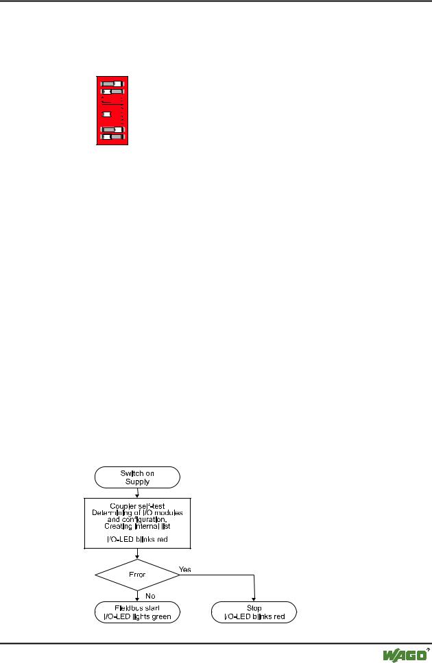
3.1.3 Operating System
Following is the configuration of the master activation and the electrical installation of the fieldbus station.
After switching on the supply voltage, the Coupler performs a self-test of all functions of its devices, the I/O module and the fieldbus interface. Following this, the I/O modules and the present configuration is determined, whereby an external, not visible list is generated.
In the event of a fault, the Coupler changes to the "Stop" condition. The "I/O" LED flashes red. After clearing the fault and cycling power, the Coupler changes to the "Fieldbus start" status and the "I/O" LED lights up green.
Fig. 3-8: Operating system 750-306 |
g012113d |
WAGO-I/O-SYSTEM 750
DeviceNet