Материал: m013500e_x06
56 • Fieldbus Coupler/Controller
Fieldbus Coupler 750-306
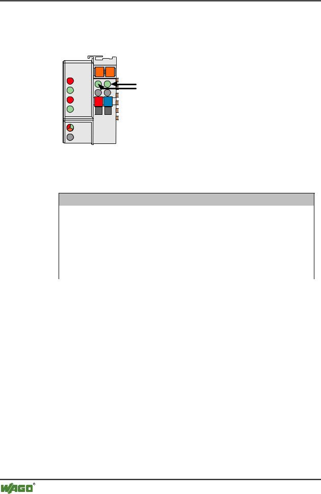
3.1.8 LED Display
The Coupler possesses several LEDs for on site display of the Coupler operating status or the complete node.
DeviceNet |
01 |
02 |
|
OVERFL |
A |
C |
C |
MS |
B |
A |
|
RUN |
|
||
|
D |
||
|
|
|
|
BUS OFF |
24V |
0V |
|
NS |
|
|
|
CONNECT |
|
|
|
I/O |
|
|
|
Fig. 3-18: Display elements 750-306 |
g030602x |
The module status (MS) and the network status (NS) can be displayed by the top 4 LED’s. They react as described in the table.
Module status (MS)
OVERFL |
RUN |
State of device |
Meaning |
(red) |
(green) |
|
|
|
|
|
|
off |
off |
no power |
No power supply to the device. |
off |
on |
device operational |
The device operates correctly. |
off |
blinking |
device in standby |
The device needs to be configured or has been partly |
|
|
|
configured. |
blinking |
off |
minor fault |
A minor fault has occurred. It exists a diagnostics. |
on |
off |
unrecoverable fault |
The device is defective, needs to be serviced or |
|
|
|
replaced. |
blinking |
blinking |
device self testing |
The device performs a built-in check. |
Table 3-1: Fault and status displays: MS |
|
||
|
|
|
|
Network status (NS) |
|
|
|
BUSOFF |
CONNECT |
State of device |
Meaning |
(red) |
(green) |
|
|
off |
off |
not powered, not online |
No power supply to the device / fieldbus supply / |
|
|
|
DeviceNet cable not connected and „Duplicate MAC |
|
|
|
ID detection“ is not yet completed. |
off |
blinking |
online, not connected |
The device operates correctly at the fieldbus. How- |
|
|
|
ever, it has not yet been integrated by a scanner. |
off |
on |
link ok online, connec- |
The device operates correctly at the fieldbus. At |
|
|
ted |
least one connection to another device has been |
|
|
|
established. |
blinking |
off |
connection time out |
A minor fault has occurred (e.g. EPR is unequal 0 |
|
|
|
during a polling connection, slave is not polled any |
|
|
|
longer). |
on |
off |
critical link failure |
The device has detected a fault (duplicated MAC ID |
|
|
|
check error). It is unable to perform any more func- |
|
|
|
tions in the network. |
Table 3-2: Fault and status displays: NS
WAGO-I/O-SYSTEM 750
DeviceNet
|
|
|
Fieldbus Coupler/Controller • 57 |
|
|
|
Fieldbus Coupler 750-306 |
|
|
|
|
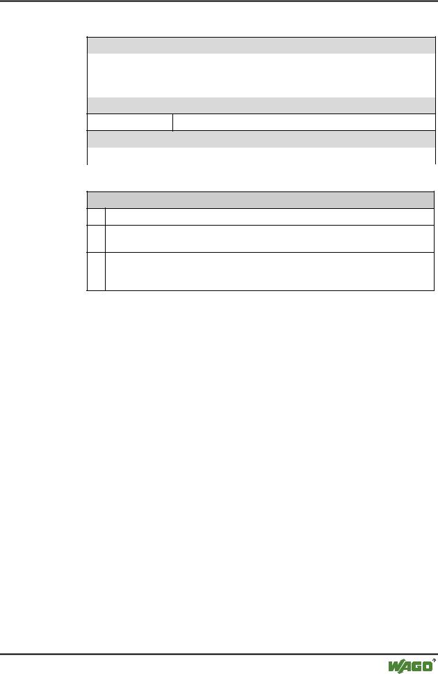
3.1.8.1 Node Status |
|
|
|
|
|
|
|
|
LED |
Color |
Meaning |
|
IO |
red /green |
The 'I/O' LED indicates the node operation and signals faults occur- |
|
|
/ orange |
ring. |
|
|
|
|
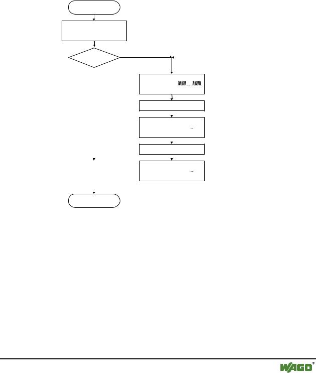
The Coupler starts after switching on the supply voltage. The "I/O" LED flashes red. Following an error free start up, the "I/O" LED changes to a green, steady light.
In the case of a fault the "I/O" LED continues blinking red. The fault is cyclically displayed with the blink code.
Switching on the power supply
Coupler/Controller starts up
“I/O”-LED is blinking
Test o.k.? |
No |
|
||||||||||||||
|
|
|
|
|
|
|
|
|
|
|
|
|
|
|
||
|
Yes |
|
|
|
|
|
|
|
|
|
|
|
|
|
|
|
|
|
|
|
|
|
|
|
|
|
|
|
|
|
|
|
|
|
|
|
“I/O” LED |
|
||||||||||||
|
|
|
1st flash sequence |
|
||||||||||||
|
|
|
(Introduction of the |
|
||||||||||||
|
|
|
error indication) |
|
||||||||||||
|
|
|
1st break |
|
||||||||||||
|
|
|
|
|
|
|
|
|
|
|
|
|
|
|
||
|
|
|
|
|
|
|
|
|
|
|
|
|
|
|
|
|
|
|
|
“I/O” LED |
|
||||||||||||
|
|
|
2nd flash sequence |
|
|
|
|
|
|
|
||||||
|
|
|
|
|
|
|
|
|
|
|
|
|
||||
|
|
|
Error code |
|
|
|
|
|
|
|
|
|
|
|
||
|
|
|
(Number of flash cycles) |
|
||||||||||||
|
|
|
|
|
|
|
|
|
|
|
|
|
|
|
||
|
|
|
|
|
|
|
|
|
|
|
|
|
|
|
|
|
|
|
|
2nd break |
|
||||||||||||
|
|
|
|
|
|
|
|
|
|
|
|
|
|
|
|
|
|
|
|
|
|
|
|
|
|
|
|
|
|
|
|
|
|
|
|
|
“I/O” LED |
|
||||||||||||
|
|
|
|
|||||||||||||
“I/O”-LED is shining |
|
3rd flash sequence |
|
|
|
|
|
|
|
|
|
|
|
|||
|
Error argument |
|
||||||||||||||
|
|
|
|
|||||||||||||
|
|
|
(Number of flash cycles) |
|
||||||||||||
|
|
|
|
|
|
|
|
|
|
|
|
|
|
|
|
|
|
|
|
|
|
|
|
|
|
|
|
|
|
|
|
|
|
ready for operation |
|
|
|
|
|
|
|
|
|
|
|
|
|
|
|
|
Fig. 3-19: Signalling the LED's node status |
g012111e |
|||||||||||||||
After overcoming a fault, restart the Coupler by cycling the power.
I/O |
Meaning |
green |
Data cycle on the internal bus |
|
|
off |
No data cycle on the internal bus |
|
|
red |
Coupler hardware defective |
|
|
red |
When starting: internal bus is initialized |
blinks |
During operation: general internal bus fault |
|
|
red |
Fault message during internal bus reset and internal fault: |
blinks cyclically |
|
|
|
WAGO-I/O-SYSTEM 750
DeviceNet

58 • Fieldbus Coupler/Controller
Fieldbus Coupler 750-306
3.1.8.2 Blink Code
Detailed fault messages are displayed with the aid of a blink code. A fault is cyclically displayed with up to 3 blink sequences.
•The first blink sequence (approx. 10 Hz) starts the fault display.
•The second blink sequence (approx. 1 Hz) following a pause. The number of blink pulses indicates the fault code.
•The third blink sequence (approx. 1 Hz) follows after a further pause. The number of blink pulses indicates the fault argument.
3.1.8.3Fault Message via the Blink Code of the I/O LED
Fault argument |
Fault description |
Fault code 1: Hardware and configuration fault |
|
0 |
EEPROM check sum fault / check sum fault in parameter area of the |
|
flash memory |
|
|
1 |
Overflow of the internal buffer memory for the inline code |
|
|
2 |
Unknown data type |
|
|
3 |
Module type of the flash program memory could not be determined / |
|
is incorrect |
|
|
4 |
Fault during writing in the flash memory |
|
|
5 |
Fault when deleting the FLASH memory |
|
|
6 |
Changed I/O module configuration found after AUTORESET |
|
|
7 |
Fault when writing in the serial EEPROM |
|
|
8 |
Invalid firmware |
|
|
9 |
Checksum error serial EPROM |
|
|
10 |
Initial error serial EPROM |
|
|
11 |
Read error serial EPROM |
|
|
12 |
Timeout error serial EPROM |
|
|
Fault code 2: Fault in programmed configuration |
|
0 |
Incorrect table entry |
|
|
Fault code 3: Internal bus command fault |
|
0 |
I/O module(s) has (have) identified internal bus command as incor- |
|
rect |
|
|
Fault code 4: Internal bus data fault |
|
0 |
Data fault on internal bus or |
|
Internal bus interruption on Coupler |
|
|
n* (n>0) |
Internal bus interrupted after I/O module n |
|
|
WAGO-I/O-SYSTEM 750
DeviceNet
Fieldbus Coupler/Controller • 59
Fieldbus Coupler 750-306
Fault code 5: Register communication fault
n* |
Internal bus fault during register communication with the I/O mod- |
|
ule n |
|
|
Fault code 6: Fieldbus specific faults
0not used
Fault code 7: I/O module not supported
n* |
I/O module not supported at position n |
|
|
* The number of blink pulses (n) indicates the position of the I/O module. I/O modules without data are not counted (i.e. supply module without diagnosis)
Example: the 13th I/O module is removed.
1.The "I/O" LED generates a fault display with the first blink sequence (approx. 10 Hz).
2.The first pause is followed by the second blink sequence (approx. 1 Hz). The "I/O" LED blinks four times and thus signals the fault code 4 (internal bus data fault).
3.The third blink sequence follows the second pause. The "I/O" LED blinks twelve times. The fault argument 12 means that the internal bus is interrupted after the 12th I/O module.
3.1.8.4Supply Voltage Status
LED |
Color |
Meaning |
A |
green |
Status of the operating voltage – system |
|
|
|
C |
green |
Status of the operating voltage – power jumper contacts |
|
|
|
There are two green LED’s in the Coupler supply section to display the supply voltage. The left LED (A) indicates the 24 V supply for the Coupler. The right hand LED (C) signals the supply to the field side, i.e. the power jumper contacts.
WAGO-I/O-SYSTEM 750
DeviceNet

60 • Fieldbus Coupler/Controller
Fieldbus Coupler 750-306
3.1.9 Technical Data
System data |
|
Max. no. of nodes |
64 with scanner |
Max. no. of I/O points |
ca. 6000 (depends on master) |
Transmission medium |
shielded Cu cable, |
|
trunk line: AWG 15, 18 (2x 0.82mm2 +2x1.7mm2) |
|
drop line: AWG 22, 24 (2x0.2mm2 +2x0.32mm2) |
Max. length of bus line |
100 m ... 500 m |
|
(depends on baud rate / on the cable) |
Baud rate |
125 kBaud, 250 kBaud, 500 kBaud |
BusCoupler connection |
5-pole male connector, series 231 (MCS) |
|
female connector 231-305/010-000/050-000 |
|
is included |
Standards and approvals |
|
UL |
E175199, UL508 |
|
E198726, UL1604 |
|
Clas I Div2 ABCD T4A |
KEMA |
01ATEX1024 X |
|
Eex nA II T4 |
Certification |
ODVA |
Conformity marking |
CE |
Accessories |
|
EDS files |
750-912 |
Miniature WSB quick marking system |
|
Technical data |
|
Max. number of I/O modules |
64 |
Input process image |
max. 512 bytes |
Output process image |
max. 512 bytes |
Configuration |
via PC or PLC |
Voltage supply |
DC 24 V (-15 % / + 20 %) |
Current consumption |
|
- via power supply terminal |
< 500 mA at 24 V |
- via CAN interface |
< 120 mA at 11 V |
Efficiency of the power supply |
87 % |
Internal power consumption |
350 mA at 5 V |
Total current for I/O modules |
1650 mA at 5 V |
Isolation |
500 V system/supply |
Voltage via power jumper contacts |
DC 24 V (-15 % / + 20 %) |
Current via power jumper contactmax |
DC 10 A |
Dimensions (mm) W x H x L |
51 x 65* x 100 (*from top edge of mounting rail) |
Weight |
ca. 195 g |
EMC interference resistance |
acc. EN 50082-2 (95) |
EMC interference transmission |
acc. EN 50081-2 (94) |
WAGO-I/O-SYSTEM 750
DeviceNet