Материал: m013802e_b
5.2.5 Application example
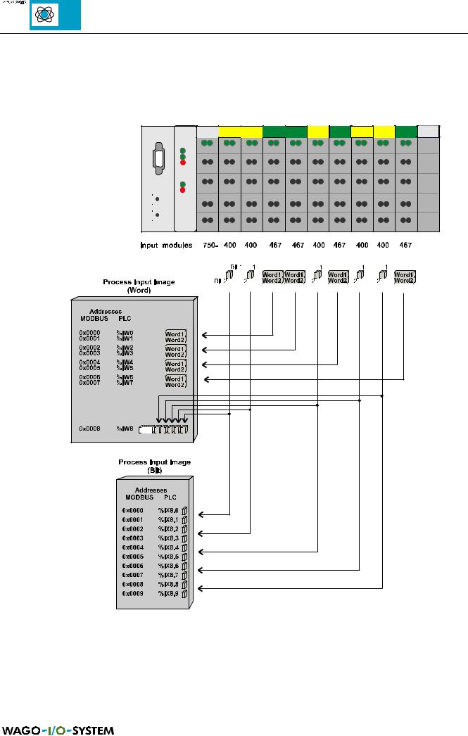
The following figure is an example of a process input image. The configuration comprises of 10 digital and 8 analog inputs. The process image thus has a data length of 8 words for the analog and 1 word for the digital inputs, i.e. 9 words in total.
Fig. 5.11: Example for process input image, controller
50 |
MODBUS / Configuration |
15.12.99
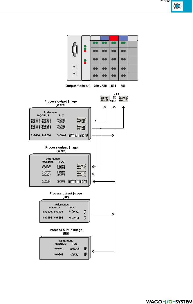
The following example for the process output image comprises of 2 digital and 4 analog outputs. It comprises of 4 words for the analog and one word for the digital outputs.
Fig. 5.12: Example for process output image, controller
MODBUS / Configuration |
51 |
15.12.99
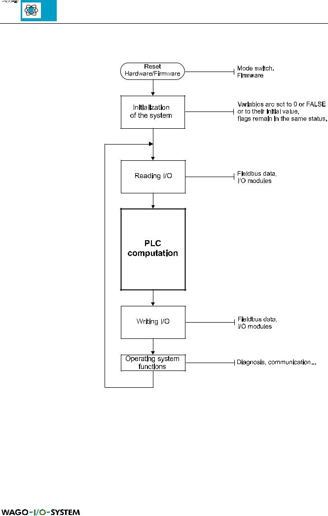
5.2.6 Controller operating system
Fig. 5.13: Operating system, controller
52 |
MODBUS / Configuration |
15.12.99

5.3 Common coupler/controller functions
5.3.1 Implemented MODBUS functions
The following table shows the functions which support both the MODBUS coupler as well as the MODBUS controller:
Function |
Function |
Description |
|
code |
|
|
|
|
|
|
|
0x01 |
Read Coil Status |
Read input bits and output bits as an octet string. |
Functions are |
|
|
|
|
0x02 |
Read Input Status |
Read input bit as an octet string. |
identical |
|
|||
|
|
|
|
0x03 |
Read Holding Registers |
Read number of input words. |
Functions are |
|
|
|
|
0x04 |
Read Input Registers |
Read number of input words. |
identical |
|
|||
|
|
|
|
0x05 |
Force Single Coil |
Write output bit. |
|
|
|
|
|
0x06 |
Preset Single Register |
Writes a value in an output word. |
|
|
|
|
|
0x0B |
Fetch Comm Event Ctr |
Read status word and event counter. |
|
|
|
|
|
0x0F |
Force Multiple Coils |
Writes a number of output bits. |
|
|
|
|
|
0x10 |
Preset Multiple Regs |
Writes a number of output words. |
|
|
|
|
|
Table 5.29: Implemented functions
MODBUS / Configuration |
53 |
15.12.99
5.3.1.1 Use of the MODBUS functions
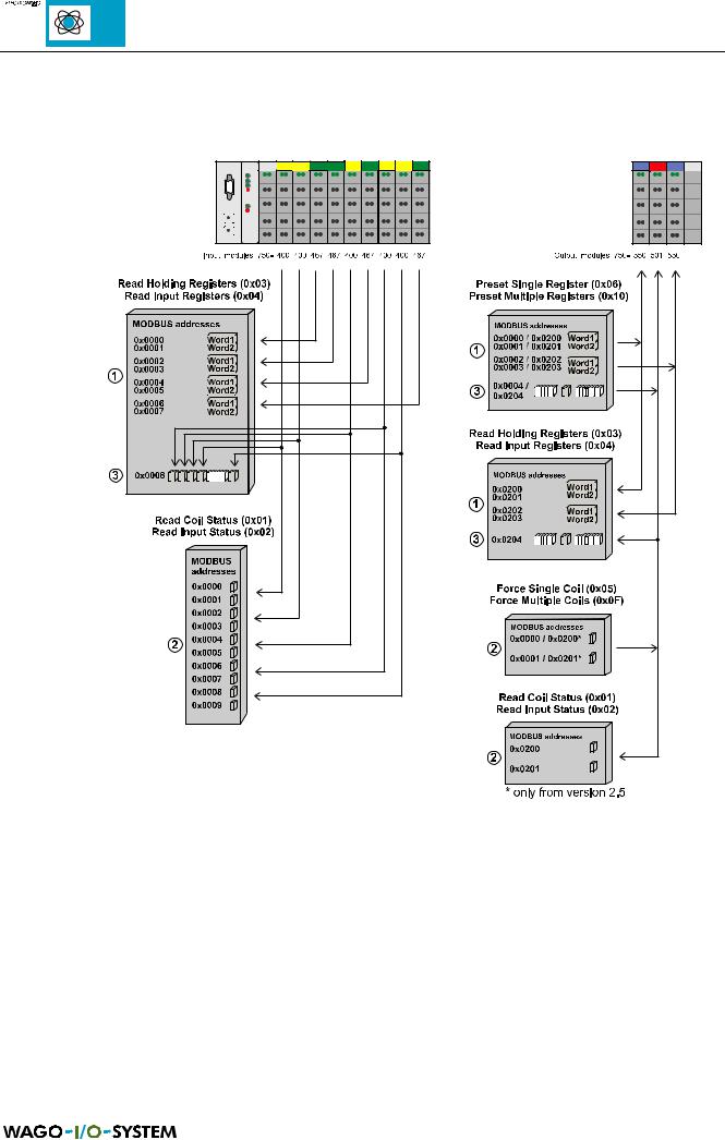
The graphical review shows the MODBUS functions which have access to process illustration data.
Fig. 5.14: Review of MODBUS functions, e.g. with coupler
It is to be recommended to access the analog signals with register functions and binary signals with coil functions . If access is also required to reading and writing binary signals with register functions , the addresses are displayed as soon as a further analog modules are fitted.
54 |
MODBUS / Configuration |
15.12.99