Материал: m013802e_b
5.2.2.3Data exchange between I/O modules and PLC functionality
Fig. 5.9: Data exchange between I/O modules and PLC functionality
MODBUS / Configuration |
45 |
15.12.99
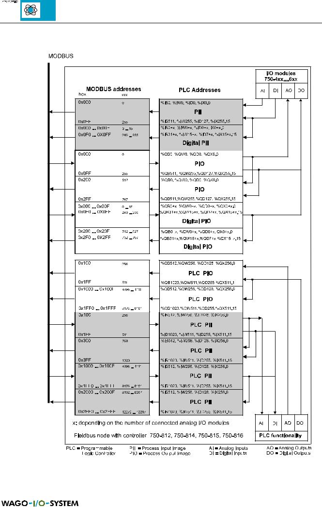
5.2.2.4Address review
Fig. 5.10: Address review, controller
46 |
MODBUS / Configuration |
15.12.99
5.2.3 Absolute addresses for inputs, outputs and flags
The direct display of individual memory cells (absolute addresses) in accordance with IEC 1131-3 is made using special character strings in accordance with the following table:
Position |
Character |
Designation |
Comments |
|
|
|
|
1 |
% |
Starts absolute address |
|
|
|
|
|
2 |
I |
Input |
|
|
Q |
Output |
|
|
M |
Flag |
|
|
|
|
|
3 |
X* |
Single bit |
Data width |
|
B |
Byte (8 Bits) |
|
|
W |
Word (16 Bits) |
|
|
D |
Double word (32 Bits) |
|
|
|
|
|
4 |
|
Address |
|
|
|
|
|
* The character ‘X’ for bits can be deleted
Table 5.21: Absolute addresses
Enter the absolute address character strings without blanks!
Address range for I/O module data:
Data width |
Address |
|
|
|
|
|
|
|
|
|
|
|
|
|
|
|
|
|
|
|
|
|
|
|
|
|
|
|
|
|
|
||||
Bit |
0.0 ... 0.15 |
|
1.0 ... 1.15 |
..... |
|
254.0 ... 254.15 |
|
255.0 ... 255.15 |
|||||||||
|
|
|
|
|
|
|
|
|
|
|
|
|
|
|
|
|
|
Byte |
0 |
|
1 |
|
2 |
|
3 |
..... |
|
..... |
508 |
|
509 |
|
510 |
|
511 |
|
|
|
|
|
|
|
|
|
|
|
|
|
|
|
|
|
|
Word |
0 |
|
|
|
1 |
..... |
|
|
254 |
|
|
255 |
|||||
|
|
|
|
|
|
|
|
|
|
|
|
|
|
|
|
|
|
DWord |
|
|
|
0 |
|
|
..... |
|
|
|
|
127 |
|
|
|||
|
|
|
|
|
|
|
|
|
|
|
|
|
|
|
|
|
|
Table 5.22: Address range for the I/O module data
Fieldbus data address range:
Data width |
Address |
|
|
|
|
|
|
|
|
|
|
|
|
|
|
|
|
|
|
|
|
|
|
|
|
|
|
|
|
|
|||
Bit |
256.0 ... 256.15 |
|
257.0 ... 257.15 |
..... |
|
510.0 |
... 510.15 |
|
511.0 ... 511.15 |
|||||||
|
|
|
|
|
|
|
|
|
|
|
|
|
|
|
|
|
Byte |
512 |
|
513 |
|
514 |
|
515 |
..... |
..... |
1020 |
|
1021 |
|
1022 |
|
1023 |
|
|
|
|
|
|
|
|
|
|
|
|
|
|
|
|
|
Word |
256 |
|
|
|
257 |
..... |
|
|
510 |
|
|
511 |
||||
|
|
|
|
|
|
|
|
|
|
|
|
|
|
|
|
|
DWord |
|
|
|
128 |
|
|
..... |
|
|
|
|
255 |
|
|
||
|
|
|
|
|
|
|
|
|
|
|
|
|
|
|
|
|
Table 5.23: Address range for fieldbus data
MODBUS / Configuration |
47 |
15.12.99
Address range for flags (retain):
Data width |
Address |
|
|
|
|
|
|
|
|
|
|
|
|
|
|
|
|
|
|
|
|
|
|
|
|
|
|
|
|
|
|
||||
Bit |
0.0 ... 0.15 |
|
1.0 ... 1.15 |
|
|
..... |
4094.0 ... 4094.15 |
4095.0 ... 4095.15 |
|||||||||
|
|
|
|
|
|
|
|
|
|
|
|
|
|
|
|
|
|
Byte |
0 |
|
1 |
|
2 |
|
3 |
..... |
|
..... |
8188 |
|
8189 |
|
8190 |
|
8191 |
|
|
|
|
|
|
|
|
|
|
|
|
|
|
|
|
|
|
Word |
0 |
|
|
1 |
|
|
|
..... |
|
4094 |
|
|
4095 |
||||
|
|
|
|
|
|
|
|
|
|
|
|
|
|
|
|
|
|
DWord |
|
|
0 |
|
|
|
|
..... |
|
|
|
2047 |
|
|
|||
|
|
|
|
|
|
|
|
|
|
|
|
|
|
|
|
|
|
Table 5.24: Address range for flags
Address calculation (depending upon the word address):
Bit address: |
|
|
Word address .0 to .15 |
|
|
|
|
|
|
|
|
|
|
|
|
|
|
|
|
||||||||||||||
Byte address: |
|
|
1. Byte: 2 x Word address |
|
|
|
|
|
|
|
|
|
|
|
|
|
|
|
|
||||||||||||||
|
|
|
|
|
|
|
|
|
2. Byte: 2 x Word address + 1 |
|
|
|
|
|
|
|
|
|
|
|
|||||||||||||
DWord address: |
|
|
|
|
|
|
|
|
|
|
|
|
|
|
|
|
|
|
|
|
|
|
|
|
|
|
|
||||||
Lower section: |
|
|
Word address (even numbers) / 2 |
|
|
|
|
|
|
|
|
|
|
|
|||||||||||||||||||
Upper section: |
|
|
Word address (uneven numbers) / 2, rounded off |
||||||||||||||||||||||||||||||
Example for input absolute addresses: |
|
|
|
|
|
|
|
|
|
|
|
|
|
|
|
|
|||||||||||||||||
|
|
|
|
|
|
|
|
|
|
|
|
|
|
|
|
|
|
|
|
|
|
|
|
|
|
|
|
|
|
|
|
|
|
%IX14. |
0 |
1 |
2 |
3 |
4 |
5 |
6 |
7 |
8 |
9 |
10 |
11 |
12 |
13 |
14 |
15 |
%I15.* |
0 |
1 |
2 |
3 |
4 |
5 |
6 |
7 |
8 |
9 |
10 |
11 |
12 |
13 |
14 |
15 |
|
|
|
|
|
|
|
|
|
|
|
|
|
|
|
|
|
|
|
|
|
|
|
|
|
|
|
|
|
|
|
|
|
|
|
|
%IB28 |
|
|
|
|
|
%IB29 |
|
|
%IB30 |
|
|
|
|
|
|
%IB31 |
|||||||||||||||
|
|
|
|
|
|
|
|
|
|
|
|
|
|
|
|
|
|
||||||||||||||||
|
|
|
|
|
|
|
%IW14 |
|
|
|
|
|
|
|
%IW15 |
||||||||||||||||||
|
|
|
|
|
|
|
|
|
|
|
|
|
|
|
|
|
|
|
|
|
|
|
|
|
|
|
|
|
|
|
|
|
|
|
|
|
|
|
|
|
|
|
|
|
|
|
|
|
|
%IDW7 |
|
|
|
|
|
|
|
|
|
|
|
|
|
|
|
|
|
|
|
|
|
|
|
|
|
|
|
|
|
|
|
|
|
|
|
|
|
|
|
|
|
|
|
|
|
|
|
|
|
|
|
* The character ‘X’ for single bits can be deleted
Table 5.25: Example for input absolute addresses
Example for output absolute addresses:
%QX5. |
0 |
1 |
2 |
3 |
4 |
5 |
6 |
7 |
8 |
9 |
10 |
11 |
12 |
13 |
14 |
15 |
%Q6.* |
0 |
1 |
2 |
3 |
4 |
5 |
6 |
7 |
8 |
9 |
10 |
11 |
12 |
13 |
14 |
15 |
|
|
|
|
|
|
|
|
|
|
|
|
|
|
|
|
|
|
|
|
|
|
|
|
|
|
|
|
|
|
|
|
|
|
|
|
%QB10 |
|
|
|
|
%QB11 |
|
|
%QB12 |
|
|
|
|
|
|
|
%QB13 |
|||||||||||||||
|
|
|
|
|
|
|
|
|
|
|
|
|
|
|
|
|
|
||||||||||||||||
|
|
|
|
|
|
|
%QW5 |
|
|
|
|
|
|
|
%QW6 |
||||||||||||||||||
|
|
|
|
|
|
|
|
|
|
|
|||||||||||||||||||||||
|
|
|
|
%QDW2 (upper section) |
|
|
|
|
|
QDW3 (lower section) |
|||||||||||||||||||||||
|
|
|
|
|
|
|
|
|
|
|
|
|
|
|
|
|
|
|
|||||||||||||||
* The character ‘X’ for |
single bits can be deleted |
|
|
|
|
|
|
|
|
|
|
|
|
|
|
|
|
||||||||||||||||
|
|
|
|
|
|
|
|
|
|
|
|
|
|
|
|
|
|||||||||||||||||
Table 5.26: Example for output absolute addresses |
|
|
|
|
|
|
|
|
|
|
|
|
|
|
|
|
|||||||||||||||||
Example for flag absolute addresses:
%MX11. |
0 |
1 |
2 |
3 |
4 |
5 |
6 |
7 |
8 |
9 |
10 |
11 |
12 |
13 |
14 |
15 |
%M12.* |
0 |
1 |
2 |
3 |
4 |
5 |
6 |
7 |
8 |
9 |
10 |
11 |
12 |
13 |
14 |
15 |
|
|
|
|
|
|
|
|
|
|
|
|
|
|
|
|
|
|
|
|
|
|
|
|
|
|
|
|
|
|
|
|
|
|
|
%MB22 |
|
|
|
|
%MB23 |
|
%MB24 |
|
|
%MB25 |
||||||||||||||||||||||
|
|
|
|
|
|
|
|
|
|
|
|
|
|
|
|
|
|
|
|
|
|
|
|
||||||||||
|
|
|
|
|
|
|
%MW11 |
|
|
|
|
|
|
|
%MW12 |
|
|
|
|
|
|
||||||||||||
|
|
|
|
|
|
|
|
|
|
||||||||||||||||||||||||
|
|
|
|
%MDW5 (upper section) |
|
|
|
|
%MDW6 (lower section) |
||||||||||||||||||||||||
|
|
|
|
|
|
|
|
|
|
|
|
|
|
|
|
|
|
|
|||||||||||||||
* The character ‘X’ for |
single bits can be deleted |
|
|
|
|
|
|
|
|
|
|
|
|
|
|
|
|
||||||||||||||||
|
|
|
|
|
|
|
|
|
|
|
|
|
|
|
|
|
|||||||||||||||||
Table 5.27: Example for flag absolute addresses |
|
|
|
|
|
|
|
|
|
|
|
|
|
|
|
|
|||||||||||||||||
48 MODBUS / Configuration
15.12.99

5.2.4 Addressing the I/O modules
∙The arrangement of the I/O modules in a node is optional.
∙Addressing of the I/O modules relates to the attendant controller.
∙Addressing is organised word for word and starts both for inputs as well as outputs with word address ‘0’.
∙The I/O module addressing corresponds to the arrangement order behind the controller. Addressing starts with the I/O module, which occupy one or more words per channel. The I/O module addresses which occupy one or two bits per channel then follow. For the number of input and output bits or bytes please refer to the corresponding I/O module data sheets.
∙Addressing of the I/O modules which occupy one or two bits per channel is also made word for word. 16 inputs or outputs each are arranged in one word. If less channels are available the remaining bits of the word remain free or are reserved for extensions.
∙If a node is extended by additional I/O modules for which one or more words are assigned per channel, the I/O module addresses are displayed accordingly by one or two bits per channel.
Data width ÿ 1 word / channel |
Data width = 1 Bit / channel |
Analog input modules |
Digital input modules |
Analog output modules |
Digital output modules |
Input modules for thermal elements |
Digital output modules with diagnosis (2 Bit / channel) |
Input modules for resistance sensors |
Power supply module with fuse holder / diagnosis |
Pulse width output modules |
Solid State power relay |
Interface modules |
Relay output modules |
Up/down counter |
|
I/O modules for angle and path measurement |
|
Table 5.28: Data width of I/O modules |
|
MODBUS / Configuration |
49 |
15.12.99