Материал: m013802e_b

5.2.1.8 Watchdog
The watchdog serves for monitoring the data transfer between the higher ranking controls and the controller. If no communication occurs after a preset time, the controller can be run into a secured status.
The watchdog is switched on via the NOWATCHDOG input.
Watchdog |
NOWATCHDOG |
|
Value |
switched on |
FALSE |
|
|
switched off |
TRUE |
|
|
Table 5.19: Watchdog, controller
Watchdog activated is the standard setting.
The watchdog selection is described is detail in chapter 5.3.2.
40 |
MODBUS / Configuration |
15.12.99
5.2.2 Data exchange between MODBUS master and controller
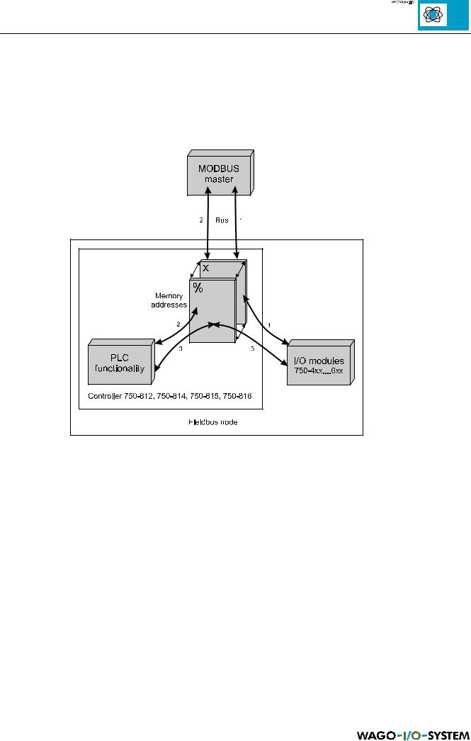
The controller mainly comprises of PLC functionality as well the interface to the I/O modules and to the MODBUS. Data is exchanged between the PLC functionality, I/O modules and the MODBUS master. This system operates with two different address formats.
Fig. 5.6: Data exchange between MODBUS master and controller
1Data exchange between MODBUS master and I/O modules (hexadecimal or decimal display of the addresses, x)
2Data exchange between the MODBUS master (hexadecimal or decimal display of the address, x) and PLC functionality (absolute addresses, %)
3Data exchange between I/O modules and PLC functionality (absolute addresses, %)
MODBUS / Configuration |
41 |
15.12.99
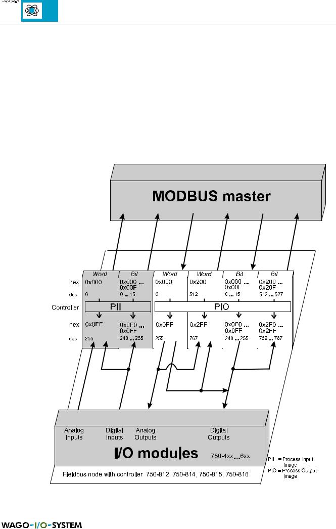
5.2.2.1 Data exchange between MODBUS master and I/O modules
The data exchange between the MODBUS master and the I/O modules is made by reading and writing in bits or bytes.
The controller handles four different types of process data:
∙Input words
∙Output words
∙Input bits
∙Output bits
The following figure shows the data word addresses in the process illustration of the inputs and outputs:
Fig. 5.7: Data exchange between the MODBUS master and I/O modules
42 |
MODBUS / Configuration |
15.12.99
The word for word access to the digital input and output modules is made in accordance with the following table:
Digital inputs/ |
16. |
15. |
14. |
13. |
|
12. |
11. |
10. |
9. |
8. |
|
7. |
6. |
5. |
|
4. |
3. |
2. |
1. |
outputs |
|
|
|
|
|
|
|
|
|
|
|
|
|
|
|
|
|
|
|
|
|
|
|
|
|
|
|
|
|
|
|
|
|
|
|
|
|
|
|
Process data word |
Bit |
Bit |
Bit |
Bit |
|
Bit |
Bit |
Bit |
Bit |
Bit |
|
Bit |
Bit |
Bit |
|
Bit |
Bit |
Bit |
Bit |
|
15 |
14 |
13 |
12 |
|
11 |
10 |
9 |
8 |
7 |
|
6 |
5 |
4 |
|
3 |
2 |
1 |
0 |
|
|
|
|
|
|
|
|
|
|
|
|
|
|
|
|
|
|
||
Byte |
|
|
|
High-Byte |
|
|
|
|
|
|
|
Low-Byte |
|
|
|
||||
|
|
|
|
|
D1 |
|
|
|
|
|
|
|
|
D0 |
|
|
|
||
Table 5.20: Allocation of digital inputs/outputs to process data word, controller |
|
|
|
|
|
|
|
|
|||||||||||
Common access of MODBUS master and PLC functionality to outputs
яюэьыъщэш
The process illustration of outputs is described both by the MODBUS master as well as by the PLC functionality, so that the I/O module outputs can be set or reset from both sides. In the case of simultaneity no priority exists. Design the user programs of the MODBUS master and the PLC functionality such that conflicting instructions for simultaneous setting or resetting of outputs is excluded. Applicable in all cases is that the individual instruction of the process illustration processed last will be written over.
MODBUS / Configuration |
43 |
15.12.99
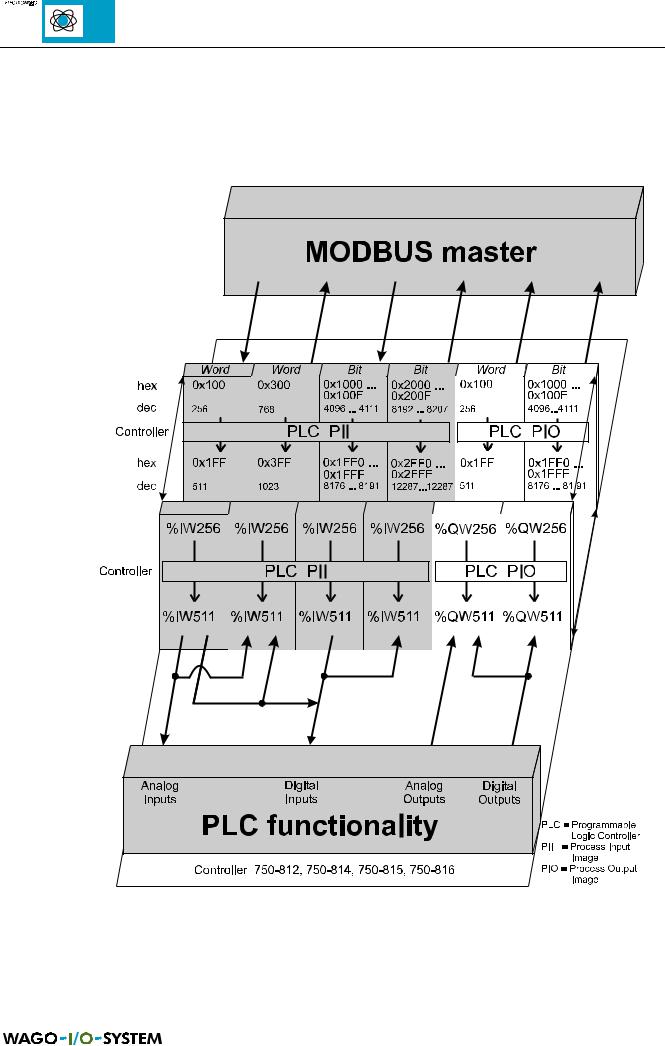
5.2.2.2 Data exchange between MODBUS master and PLC functionality
The fieldbus data in the MODBUS master and in the PLC functionality have different address formats. The addresses of the MODBUS master are displayed hexadecimal or decimal. The PLC functionality uses absolute addresses.
Fig. 5.8: Data exchange between MODBUS master and PLC functionality
44 |
MODBUS / Configuration |
15.12.99