Материал: m013802e_b
6.2 MODBUS LED
Fig. 6.3: MODBUS LED
The four following LEDs indicate the status of the coupler/controller.
Status |
LED |
State |
Description |
|
|
|
|
Node is ready for communication |
ON |
shining |
The node is working normally. The LED is out for a short time |
|
|
|
when the receiver receives an incomplete frame or a frame for |
|
|
|
another node. |
|
|
|
|
Node transmits data |
TXD |
blinking |
The node transmits a frame. |
|
|
|
|
Node receives data |
RXD |
shining |
The node receives a frame with own slave-address or |
|
|
|
broadcast. |
|
|
|
|
Node detects an frame with error |
CRC |
blinking |
The received error code differs from the calculated code. The |
code |
|
|
information in the received frames when Error Check is |
|
|
|
activated. |
|
|
|
|
Only controller: |
|
|
|
Flash |
CRC |
shining |
The user programme is transferred from RAM to Flash |
|
|
|
|
Table 6.2: : Status and error indication |
|
|
|
You have access to the diagnosis functions via the following register too:
Register |
Name |
Access |
Length |
Default |
Description |
address |
|
|
|
|
|
|
|
|
|
|
|
0x1020 |
LedErrCode |
read |
2++ |
pu |
See LED description error code |
|
|
|
|
0x0000 |
|
|
|
|
|
|
|
0x1021 |
LedErrArg |
read |
1 |
pu |
See LED description error code |
|
|
|
|
0x000 |
|
|
|
|
|
|
|
Table 6.3: Register for diagnosis functions |
|
|
pu: standard value in case of voltage connection |
||
MODBUS / Start-up and diagnosis |
75 |
15.12.99
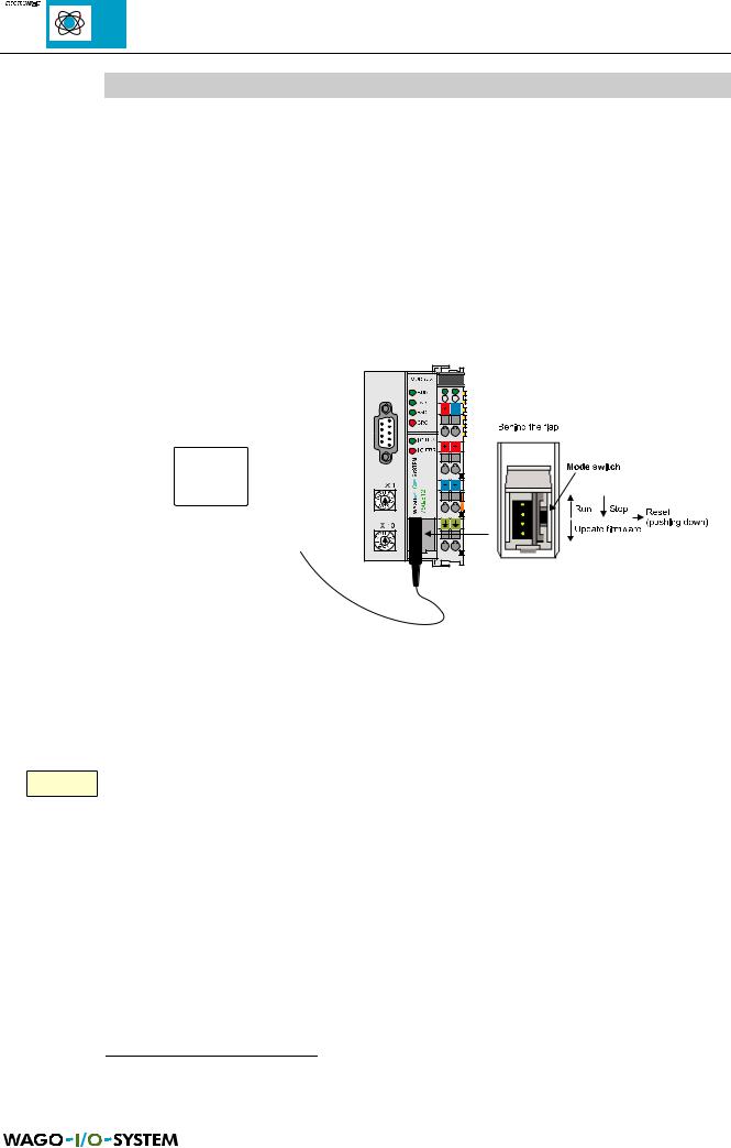
6.3 Starting up the controller with WAGO-I/O-PRO
The starting-up takes place via a PC. The WAGO communication cable1 is used to establish the connection between PC (interface: COMx) and controller. The communication parameter for data exchange between controller and PC have to correspond. The following parameter are set in the controller:
∙Baud rate: 19200 bauds
∙Stop bits: 1
∙Parity: even
These parameter are set in WAGO-I/O-PRO in the window ‘communication parameter’.
Fig. 6.4: PC and controller, operating mode switch
The WAGO-I/O-PRO specific test and starting-up functions are explained in the corresponding manual2. All the following functions marked with ‘Online’ will be carried out via PC with WAGO-I/O-PRO.
яюэьыъщэш Before you log in, the station address switch must be set to ‘00’! The modified address will be taken over for the controller when you reconnect the supply
voltage.
Before loading the programme, the operating mode switch should be set to Stop or the cycle should be stopped with ‘Online’ ‘Stop’ .
1Communication cable, Order No. 750-920 (part of the programming tools IEC 1131-3)
2WAGO-I/O-PRO manual, English, Order No. 750-120/000-002
76 |
MODBUS / Start-up and diagnosis |
15.12.99

The programme processing can be started in each position of the operating mode switch with ‘Online’ ‘Start’ and be stopped with ‘Online’ ‘Stop’ .
ATTENTION!
In case of ‘Online’ ‘Stop’ or when you set the operating mode switch from run to stop, the outputs (e. g. for motor contactors or valves) which are still set remain set! Switching-off commands coming from the software, e. g. via sensors, are then ineffective because the program is not executed any more !
(The change in operating mode is taking place internally at the end of the program cycle).
MODBUS / Start-up and diagnosis |
77 |
15.12.99

|
|
|
|
|
|
|
|
|
|
|
|
|
|
|
|
|
|
|
|
|
|
|
|
78 |
MODBUS / Start-up and diagnosis |
||
15.12.99

7 General Conditions
To ensure the good operation of the WAGO-I/O-SYSTEM the following general conditions have to be fulfilled.
7.1 Transport and storage conditions
The following declarations concern I/O modules which are transported and stored in the original package.
Conditions |
Allowed values |
|
|
Free fall |
≤ 1m |
|
|
Temperature |
-40°C to +70°C |
|
|
Relative humidity |
5 % to 95 % (without condensation) |
|
|
Table 7.1: Transport and storage conditions |
|
7.2 Climatic conditions
The modules of the WAGO-I/O-SYSTEMÿ must not be used without taking suitable actions:
-under heavy conditions,
e.g. very dusty rooms, corroding atmosphere or gases
-in places with a high concentration of ionisation.
Working temperature: |
0°C to + 55°C |
|
Relative humidity |
|
|
in operation: |
5 % to 95 % (without condensation) |
|
Mounting: |
Horizontal if possible |
|
|
(for a better ventilation) |
|
Resistance to |
|
|
harmful substances: |
Tested in accordance with |
IEC 68-2-42 |
|
|
IEC 68-2-43 |
MODBUS / General conditions |
79 |
15.12.99