Материал: m013500e_x06
96 • Feldbus Coupler/Controller
Fieldbus Controller 750-806
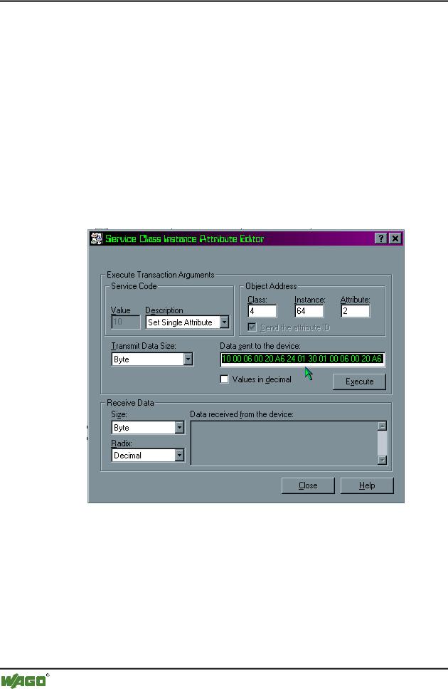
In this case, check the entries for class, instance and attribute, the DeviceNet connection and the configuration.
6.In the "Description" dialog box, select the "Set Single Attribute" utility and enter the following values in the "Object Address" dialog boxes:
- "Class": 4
–"Instance": 64 (64 hexadecimal = 100 decimal)
–"Attribute": 2.
7.Click in the " Data Sent to the device" dialog box and enter the following values in hexadecimal:
10 00 06 00 20 A6 24 01 30 01 10 00 06 00 20 A6 24 02 30 01
The path is described by:
0x20 CC (Class) 0x24 II (Instance) 0x30 AA (Attribute)
8.Click on the "Execute" button to define the mapping.
If the mapping was successful, the fieldbus node sends a “performance” confirmation.
If a fault has occurred, you will receive a fault message.
In the event of a communication or reply fault, check the DeviceNet connection and whether or not the instance was correctly set.
WAGO-I/O-SYSTEM 750
DeviceNet
Feldbus-Koppler/-Controller • 97
Fieldbus Controller 750-806
9.Click on the "Close" button. The dialog window is closed.
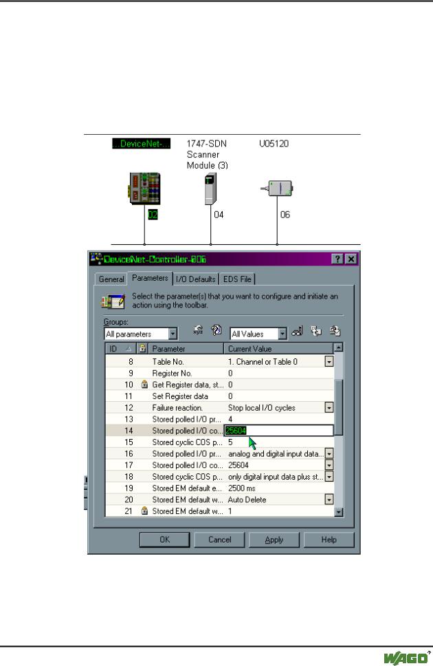
10.To parameterize the Controllers, double-click on the graphic symbol of the fieldbus node 750-806.
11.Select the "Parameters" register and “All parameters” in the "Groups" dialog box.
12.Use the scroll bar to move down to the ID#13 and #ID14 addresses.
ID#13 is a pointer for the inputs (Default = 4).
This parameter is changed when the inputs are mapped for the master. This is not required due to the fact that the inputs are only read and not written.
WAGO-I/O-SYSTEM 750
DeviceNet

98 • Feldbus Coupler/Controller
Fieldbus Controller 750-806
ID#14 is a pointer for the outputs (Default = 1).
This parameter is changed in order to point on the dynamic mapping of the outputs that are mapped in the dynamic assembly instance 100dec. (0x64hex).
13.Do not change the pre-set standard value 4 of the ID#13.
Enter 25604 decimal for the ID#14 to direct the pointer on the dynamic assembly output mapping.
The value 25604 corresponds to the hexadecimal writing 0x6404. 04 (Low Byte) = Class type
64 (High Byte) = 100 decimal instance number
14.Change the value for the ID#39. Select "Dynamic created instances are stored in non volatile memory", to retain the storage of the configuration for the Dynamic Assembly even following a voltage failure of the Controller.
15.To take over the pre-set parameters into the Controller, select the following parameter in the right-hand control box in the "Parameters" register:
"All Values", then click on the "Download parameters to the device" symbol which is located on the far right next to the dialog box.
16.Confirm the setting by clicking on the "OK" button. The dialog window is closed.
17.Then switch the supply voltage of the Controller off and on again. Now the fieldbus node is ready for networked communication.
WAGO-I/O-SYSTEM 750
DeviceNet
Feldbus-Koppler/-Controller • 99
Fieldbus Controller 750-806
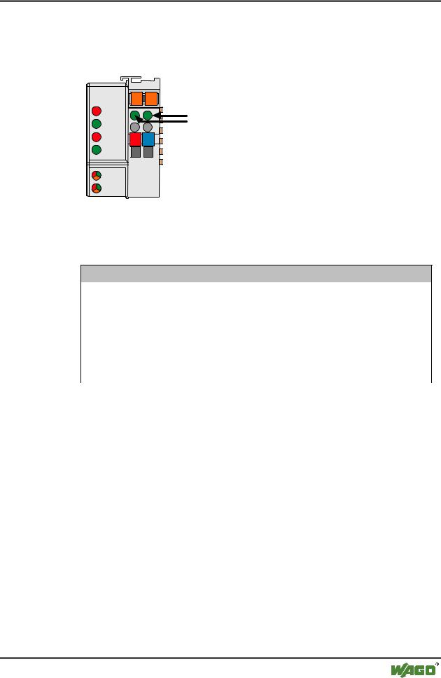
3.2.10LED Display
The Controller possesses several LEDs for on site display of the Controller operating status or the complete node.
DeviceNet |
01 |
02 |
|
|
OVERFL |
A |
C |
C |
|
MS |
B |
A |
|
|
RUN |
|
|
||
|
D |
|
||
|
|
|
|
|
BUS OFF |
24V |
0V |
|
|
NS |
|
|
|
|
CONNECT |
|
|
|
|
I/O |
|
|
|
|
USR |
|
|
|
|
Fig. 3-34: Display elements 750-806 |
g080602x |
|||
The module status (MS) and the network status (NS) can be displayed by the top 4 LED’s. They react as described in the following tables.
Module status (MS)
OVERFL |
RUN |
State of device |
Meaning |
(red) |
(green) |
|
|
|
|
|
|
off |
off |
no power |
No power supply to the device. |
off |
on |
device operational |
The device operates correctly. |
off |
blinking |
device in standby |
The device needs to be configured or has been partly |
|
|
|
configured. |
blinking |
off |
minor fault |
A minor fault has occurred. It exists a diagnostics. |
on |
off |
unrecoverable fault |
The device is defective, needs to be serviced or |
|
|
|
replaced. |
blinking |
blinking |
device self testing |
The device performs a built-in check. |
Table 3-3: Fault and status displays: MS |
|
||
|
|
|
|
Network status (NS) |
|
|
|
BUSOFF |
CONNECT |
State of device |
Meaning |
(red) |
(green) |
|
|
off |
off |
not powered, not online |
No power supply to the device / fieldbus supply / |
|
|
|
DeviceNet cable not connected and „Duplicate MAC |
|
|
|
ID detection“ is not yet completed. |
off |
blinking |
online, not connected |
The device operates correctly at the fieldbus. How- |
|
|
|
ever, it has not yet been integrated by the scanner. |
off |
on |
link ok online, connec- |
The device operates correctly at the fieldbus. At |
|
|
ted |
least one connection to another device has been |
|
|
|
established. |
blinking |
off |
connection time out |
A minor fault has occurred (e.g. EPR is unequal 0 |
|
|
|
during a polling connection, slave is not polled any |
|
|
|
longer). |
on |
off |
critical link failure |
The device has detected a fault (duplicated MAC ID |
|
|
|
check error). It is unable to perform any more func- |
|
|
|
tions in the network. |
Table 3-4: Fault and status displays: NS
WAGO-I/O-SYSTEM 750
DeviceNet
100 • Feldbus Coupler/Controller
Fieldbus Controller 750-806
3.2.10.1.1Node Status
LED |
Color |
Meaning |
IO |
red /green |
The 'I/O' LED indicates the node operation and signals faults occur- |
|
/ orange |
ring. |
|
|
|
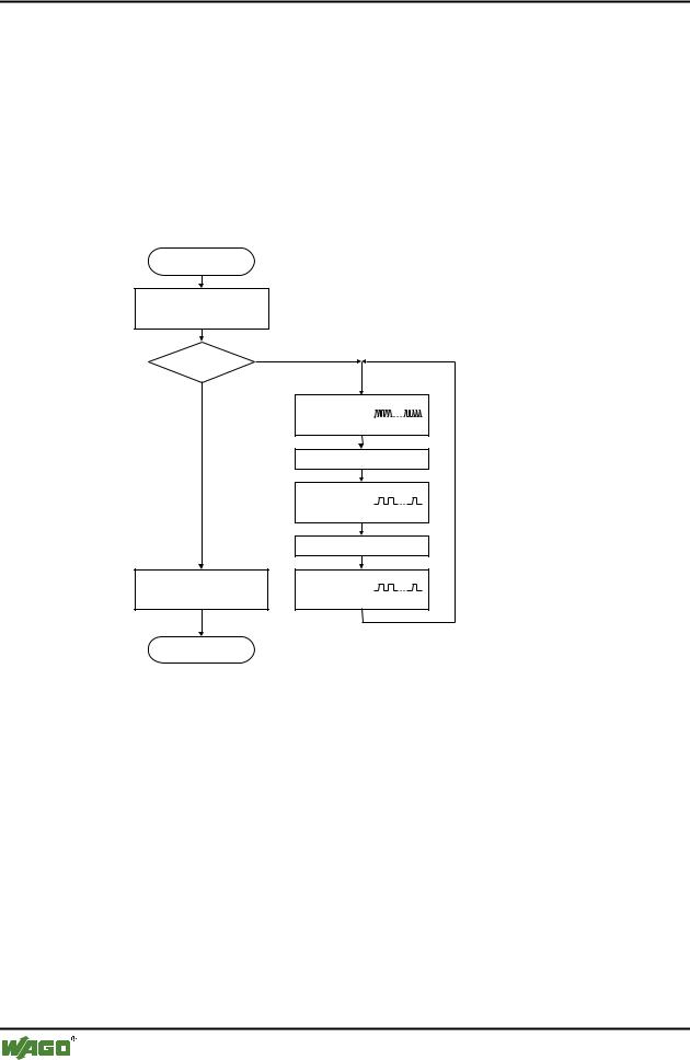
The Controller starts after switching on the supply voltage. The "I/O" LED flashes red. Following an error free start up the "I/O" LED changes to green steady light.
In the case of a fault the "I/O" LED continues blinking red. The fault is cyclically displayed with the blink code.
Versorgungsspannung
einschalten
Koppler-Hochlauf
“I/O”-LED blinkt
Fehler |
Ja |
|
|
Nein |
|
“I/O”-LED
1. Blinksequenz
(leitet opt. Anzeige eines Fehlers ein)
1. Pause
“I/O”-LED
2. Blinksequenz
Fehlercode (Anzahl Blinkimpulse)
2. Pause
“I/O”-LED
“I/O”-LED an 3. Blinksequenz
Fehlerargument (Anz. Blinkimp.)
Feldbusstart |
|
Fig. 3-35: Signalling the LED's node status |
g012111d |
After overcoming a fault, restart the Controller by cycling the power.
I/O |
Meaning |
green |
Data cycle on the internal bus |
|
|
off |
No data cycle on the internal bus |
|
|
red |
Coupler hardware defective |
|
|
red |
When starting: internal bus is initialized |
blinks |
During operation: general internal bus fault |
|
|
red |
Fault message during internal bus reset and internal fault: |
blinks cyclically |
|
|
|
orange |
MAC-ID is changed via SW and is different to the DIP switch setting |
|
|
WAGO-I/O-SYSTEM 750
DeviceNet