Материал: m013500e_x06

86 • Feldbus Coupler/Controller
Fieldbus Controller 750-806
3.2.7.5 Change MAC ID by SW
The MAC ID of the Controller can be changed via the network using the software (e.g. WAGO NETCON, RS NetWorx). For this purpose, the node address is stored in non-volatile memory. Should the address set at the DIP switch differ from the one set via the network using the software, the I/O LED changes its colour to orange.
To reset the software default address, the invalid address 64 is entered in class 3, instance 1, attribute 1.
Subsequently, the Controller has its MAC ID that is set at the DIP switch.
3.2.7.6 Heartbeat
The heartbeat function permits a node to cyclically transmit a so-called heartbeat message and, in this manner, to signal its communication ability to all members in the network.
If a responsible heartbeat consumer does not receive a message within a predefined time (Heartbeat Consuming Time), this is registered as a heartbeat fault. The relationship between producer and consumer of a Heartbeatmessage can be configured by entries in the object directory, so the time between two Heartbeat messages can be entered in Class 0x01, Instance 1, Attribut ID 10 (0x0A).
3.2.7.7 Bit-Strobe
The bit strobe I/O connection is always a 1 to n multicast connection.
In other words, a master can reach with its message all slaves supporting the bit strobe command. The transfer takes place at the same time. In this manner it is possible to synchronize the slaves.
The length of this master message is limited to 8 bytes. Each node address in the net is assigned a bit within the 8 data bytes. The reaction of the slave which bit is set is specific to the application. The reaction has to be defined and it has to be known by the PLC. With its answer, each slave can return 8 bytes of data. The order of the answers depends on the reaction time of the single slave and, in addition, it depends on the particular node address. If all slaves would reply to the Bit-Strobe command at the same time, the order of sending on the CAN bus would be determined by the node address (bit arbitration).
Further information
You can find more details in chapter 5.6.2.2.1 "Bit-Strobe".
WAGO-I/O-SYSTEM 750
DeviceNet
Feldbus-Koppler/-Controller • 87
Fieldbus Controller 750-806
3.2.8 Configuration Software
To allow a connection between the PLC and the fieldbus devices, the interface modules have to be configured with the individual station file.
To this effect, the scope of the WAGO-I/O-SYSTEM 758 includes the WAGO NETCON software intended for design and configuration, start-up and diagnosis.
Further configuration software of different manufacturers include, for instance, RSNetWorx.
3.2.9 Starting-up DeviceNet Fieldbus Nodes
This chapter shows the step-by-step procedure for starting up a WAGO DeviceNet fieldbus node.
Following this will be information for programming the PFC with WAGO- I/O-PRO 32.
Attention
This description is given as an example and is limited to the execution of a local start-up of an individual DeviceNet fieldbus node.
The procedure contains the following steps:
1.Connecting the PC and fieldbus node
2.Setting the MAC ID and baud rate
3.Configuration with static and dynamic Assembly
3.2.9.1Connecting the PC and Fieldbus Node
1.Connect the assembled DeviceNet fieldbus node to the DeviceNet fieldbus PCB in your PC via a fieldbus cable and start your PC.
The 24 V field bus supply is fed by an external fieldbus network power supply over the connections V+, V- of the 5-pin fieldbus connector (MCS Series 231).
2.Start your PC.
3.2.9.2Setting the MAC ID and Baud Rate
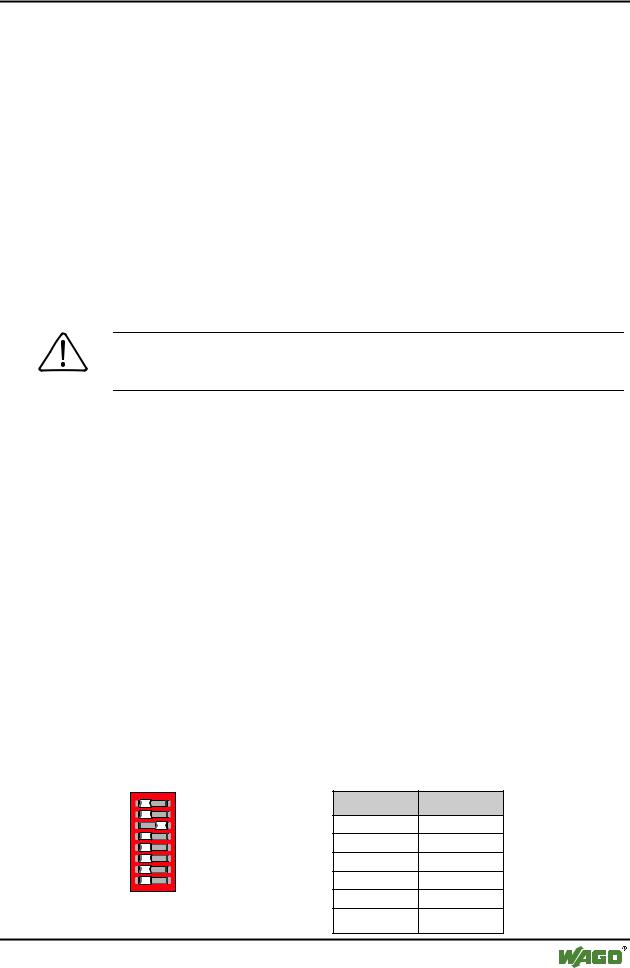
1.Use the DIP switches 1...6 to set the desired node address (MAC ID). The binary significance of the individual DIP switches increases according to the switch number.
1 2 |
ON |
DIP switch |
Value |
||
1 |
|
|
|||
3 |
|
20 |
|||
4 5 |
|
2 |
21 |
||
6 |
|
3 |
22 |
||
7 |
|
4 |
2 |
|
|
8 |
|
3 |
|||
|
|
|
|||
|
g012443x |
5 |
24 |
||
Fig. 3-30 Example: Setting the MAC |
|||||
6 |
|
|
|||
ID 4 (DIP 3 = ON). |
25 |
||||
WAGO-I/O-SYSTEM 750
DeviceNet
88 • Feldbus Coupler/Controller
Fieldbus Controller 750-806
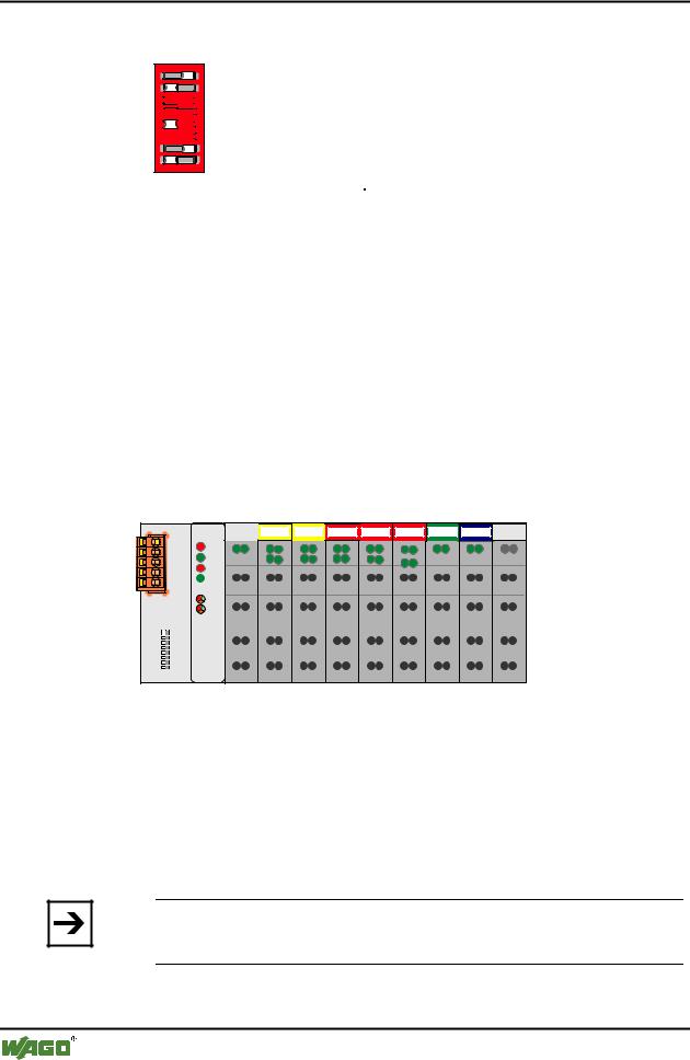
DIP switches 7 and 8 are used to set the desired baud rate.
1 |
1 2 |
ON |
|
2 |
|||
|
|
33 


44 


 ON
ON
55 


66 


7 |
7 |
|
8 |
8 |
g012541x
Fig. 3-31: Example: Setting the baud rate 250 kBaud (DIP 7 = ON) of the station with MAC ID 1.
Baud rate |
DIP7 |
DIP8 |
125 kBaud*) |
OFF |
OFF |
250 kBaud |
ON |
OFF |
|
|
|
500 kBaud |
OFF |
ON |
|
|
|
not allowed |
ON |
ON |
*) Presetting |
|
|
2.Then switch on the Controller supply voltage.
3.2.9.3Configuration with Static and Dynamic Assembly
In this example, the software RSNetWorx Rev:3.00.00 of Allan-Bradley and SLC500 with a 1747-SDN Scanner Module is used.
The inputs are mapped using the static Assembly and the outputs are mapped with the dynamic Assembly.
The node in the example consists of the following I/O modules:
1 |
2 |
3 |
4 |
5 |
6 |
7 |
8 |
DI DI |
DI DI |
DODO DODO DODO AI AI |
AO AO |
|
|
750-806 |
|
|
|
|
|
|
|
|
|
|
|
|
|
|
|
|
|
|
|
|
|
|
|
|
|
|
|
|
|
|
|
|
|
|
|
|
|
|
|
|
|
|
|
|
|
|
|
|
|
|
|
|
|
|
|
|
|
|
|
|
|
|
|
|
|
|
|
|
|
|
|
|
|
|
|
|
|
|
|
|
|
|
|||
|
|
|
|
|
|
|
|
|
|
|
|
|
|
516 |
|
|
|
|
|||
|
|
|
|
|
|
|
|
|
||
402 |
402 |
516 |
516 |
467 |
550 |
600 |
||||
Fig. 3-32: Example for a fieldbus node |
g012553x |
1.Starting Software and EDS file load
1.Start the configuration software RSNetWorx.
2.Load the EDS file "750-806_1.EDS" for the fieldbus Controller in RSNetWorx.
For this click on "Tools/ EDS Wizard" and choose the EDS-file to load.
Note
You can download the EDS file 750-806_1.EDS from the Internet under: www.wago.com
3. Now follow the Wizard instructions.
WAGO-I/O-SYSTEM 750
DeviceNet

Feldbus-Koppler/-Controller • 89
Fieldbus Controller 750-806
2.Create a New Network
1.After the EDS file has been loaded in RSNetWorx, you can start establishing your network.
For this purpose, click in the tree structure located in the left-hand screen window on the "Communication Adapter" folder.
A list of various sub-folders appears.
2.From the list of sub-folders, select the corresponding scanner available in your network (for the present example, select "1747 SDN Scanner Module").
3.Take over the selected scanner into the right-hand graphics window with a double-click or drag&drop.
The selected scanner is displayed in the right-hand screen window as a symbol.
4.Now select the DeviceNet Controller 806 in the tree structure in the "Communication Adapter" folder.
5.Also take this over into the right-hand graphic window with a double-click or drag&drop.
The Controller is added to the right-hand screen window as a second symbol.
3. RX/TX Calculation for the Mapping
The correct setting of the TX/RX configuration is a prerequisite for the perfect running of the DeviceNet network. For this purpose, the TX/RX configuration must coincide with the node configuration.
For the entry into the RX and TX fields in RSNetworx, all input bit/bytes count as a whole, as well as all output bits/bytes.
Here, individual bits are always grouped to form full bytes.
From the fieldbus master standpoint, the example node has the following data configuration:
I/O module |
RX |
TX |
750-806 DeviceNet PFC |
1 byte input status |
|
|
|
|
750-402 4-channel input |
4 bits input |
|
|
|
|
750-402 4- channel input |
4 bits input |
|
|
|
|
750-516 4- channel output |
|
4 bits output |
|
|
|
750-516 4- channel output |
|
4 bits output |
|
|
|
750-516 4- channel output |
|
4 bits output |
|
|
|
750-467 2 channel analog input |
4 bytes input |
|
|
|
|
WAGO-I/O-SYSTEM 750
DeviceNet
90 • Feldbus Coupler/Controller
Fieldbus Controller 750-806
750-550 2 channel analog output |
|
4 bytes output |
|
|
|
750-600 end module |
- |
- |
|
|
|
PFC fieldbus input variables |
|
0 bytes input |
|
|
|
PFC fieldbus output variables |
4 bytes output |
|
|
|
|
Sum |
10 bytes |
6 bytes |
|
|
|
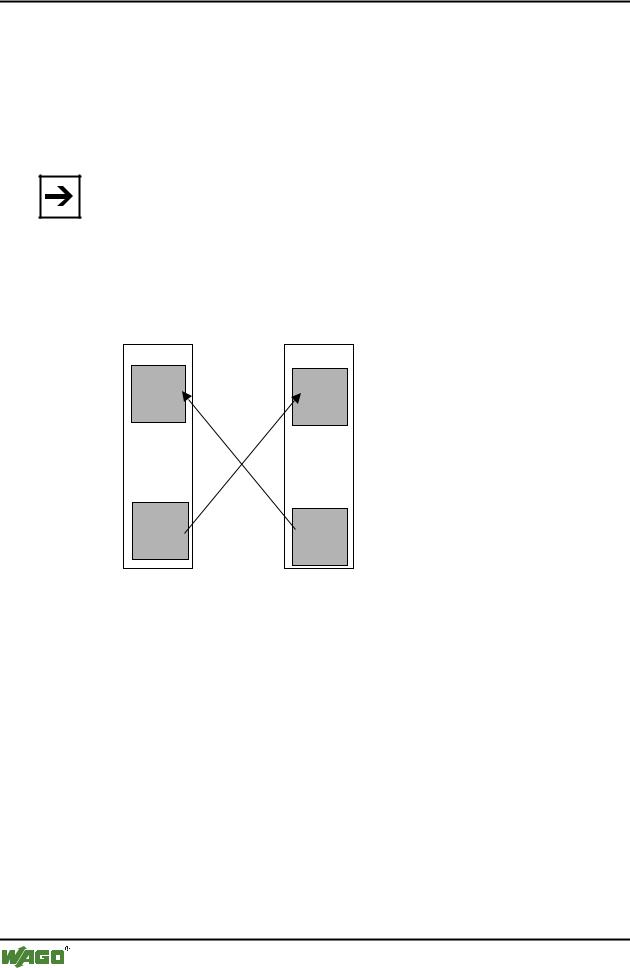
Note
PFC output variables are defined from the point of view of the programmable fieldbus Controller. These are input variables from the point of view of the fieldbus DeviceNet, which are added to the RX Settings. Accordingly, PFC input variables are output variables for IEC 61131-3 access of the field bus. For that reason they will be added to the TX Settings:
IEC 61131-3 input variable |
= |
PFC output variable |
PFC input variable |
= |
IEC 61131-3 output variable |
Feldbus |
SPS- |
Eingangs- |
variablen |
SPS- |
Ausgangs- |
variablen |
Programmierbarer
Feldbus Controller
PFC- |
Eingangs- |
variablen |
PFC- |
Ausgangs- |
variablen |
Fig. 3-33: Zusammenhang SPS-Variablen and PFC-Variablen |
g012444d |
4. Static assembly for inputs
In the present example, the master/scanner is to have access to the physical inputs and to the 4 bytes PFC output variables.
The number of input data is complemented by 4 bytes of the PFC output variables during the static assembly for the TX configuration of the scanner.
1.To be able to parameterize the Controller, double-click on the graphic symbol of the fieldbus node 750-806.
2.In the "General" register, you can assign the Controller any desired address.
To this effect, click in the input window for the address and enter the address in accordance with the address set at the Controller DIP switch.
3.The RX/TX configuration can be entered in the "Parameters" register. For this purpose, move to the "Groups" dialog box, down along the scroll bar, and select "PLC fieldbus variables".
WAGO-I/O-SYSTEM 750
DeviceNet