Материал: m013500e_x06
Feldbus-Koppler/-Controller • 91
Fieldbus Controller 750-806
4.Do not change the value for the ID#37 "PLC fieldbus Input variables" which is 0. Enter 4 for the ID#38 "PLC fieldbus Output variables".
5.Confirm the setting by clicking on the "OK" button.
6.Double-click on the scanner icon to start the configuration. The dialog window "1797-SDN Scanner Module" opens.
7.Select the "Scanlist" register card.
8.Click on the button with the arrow to the right in order to take over the DeviceNet Controller 750-806 in the left-hand window "Available Devices" into the "Scanlist" window.
9.Click on the "Edit I/O Parameters..." button.
10.Activate the poll function by clicking on the field located in front of "Polled".
The field is now ticked which permits the entry for TX and RX.
11.Enter 6 bytes in the "TX-Size" dialog box. They are receipt bytes for the inputs.
Enter 4 bytes for the PFC input variables in the "RX-Size" dialog box. The number of these bytes results from the following determinations in the dynamic assembly for the outputs. This simultaneously defines that only the PFC input variables and no physical outputs are to be written by the master.
12.Then click on the "OK" button to take over the parameters.
A window appears indicating that several I/O data will not be mapped. Confirm the question of whether or not you wish to continue by clicking on the "Yes" button.
WAGO-I/O-SYSTEM 750
DeviceNet
92 • Feldbus Coupler/Controller
Fieldbus Controller 750-806
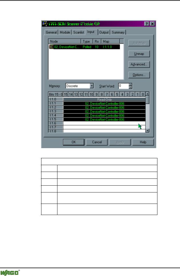
13.In the "1797-SDN Scanner Module" dialog window, select the "Input" register card. All inputs are mapped as digital inputs.
Mapped Inputs
I:1.0 1 Word Reserved for Scanner Module
I:1.1 1 Word Analog Input Channel 1
I:1.2 1 Word Analog Input Channel 2
I:1.3 |
1 Byte Status | 1 Byte Digital Inputs |
I:1.4 1 Word IEC 61131-3 input variable 1 (or PFC output variable 1)
I:1.5 1 Word IEC 61131-3 input variable 2 (or PFC output variable 2)
WAGO-I/O-SYSTEM 750
DeviceNet
Feldbus-Koppler/-Controller • 93
Fieldbus Controller 750-806
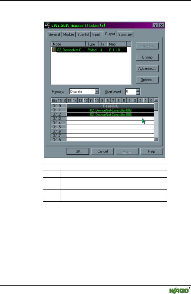
14.In the "1797-SDN Scaner Module" dialog window, select the "Output" register card. All outputs are mapped as digital outputs.
Mapped Outputs
O:1.0 1 Word Reserved for Scanner Module
O:1.1 1 Word IEC 61131-3 output variable 1 (or PFC input variable 1)
O:1.2 1 Word IEC 61131-3 output variable 2 (or PFC input variable 2)
WAGO-I/O-SYSTEM 750
DeviceNet
94 • Feldbus Coupler/Controller
Fieldbus Controller 750-806
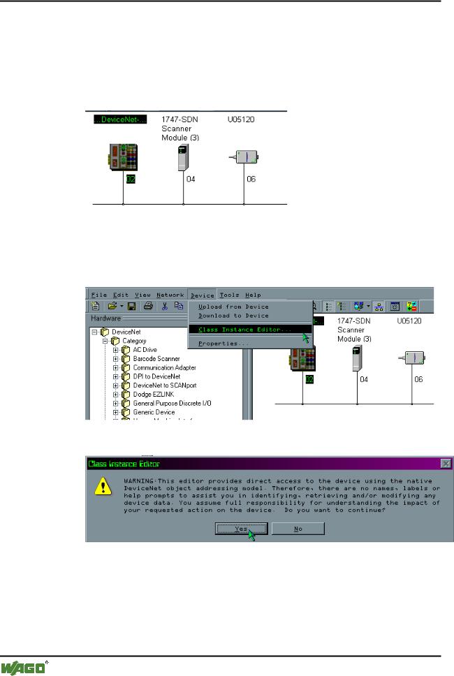
5. Dynamic assembly for the outputs
The dynamic assembly is used to map those data which are to be transmitted via the fieldbus. They are stored as classes, instances and attributes.
1.In the graphical display, click on the symbol of the fieldbus Controller 750806 so that the symbol is marked.
2.Then click on the “Class Instance Editor...” menu point in the "Device" menu.
A window displaying a warning appears:
WAGO-I/O-SYSTEM 750
DeviceNet
Feldbus-Koppler/-Controller • 95
Fieldbus Controller 750-806
Note
This editor changes parameters in the Controller.
For this reason, ensure that all data is entered consistently either as hexadecimal or decimal. If the data number format is not consistent, data loss can result up to a total functional failure of the Controller.
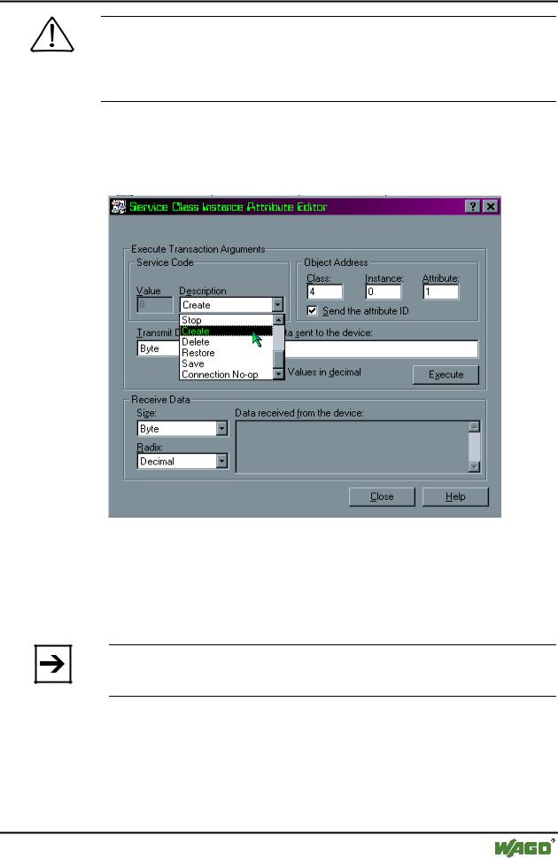
3.Confirm the warning information by clicking on the "Yes" button. The dialog window "Service Class Instance Attribute Editor" appears.
4. In the "Description" dialog box select the "Create" utility and enter the following values in the dialog boxes for the "Object Address":
- "Class": 4
–"Instance": 0
–"Attribute": 1.
Note
Do not click on the "ENTER" key, because this will close the dialog window so that it has to be reopened.
5.Click on the "Execute" button to create the instance for the dynamic assembly.
If the setting was successful, the fieldbus node will send the instance number = 100 0.
If a fault has occurred, you will receive a fault message.
WAGO-I/O-SYSTEM 750
DeviceNet