Материал: m013500e_x06

106 • DeviceNet
Description
5 DeviceNet
5.1 Description
DeviceNet is a networking concept in the device level based on the serial bus system CAN (Controller Area Network). It is particularly distinguished by the problem-free addition and removal of devices, from simple light barriers up to complex motor controls during operation. DeviceNet is mainly used in industrial automation and for robot controls.
The Data Link Layer, i.e. the physical and data storage layer, is defined in the CAN specification. The telegram architecture is described. However, there is no information about the application layer.
This is where DeviceNet comes into play. It describes the defined meaning of the data transmitted in the application layer.
The Open DeviceNet Vendor Association (abridged: ODVA) is the user organisation for DeviceNet. In a specification, the ODVA DeviceNet is defined as a uniform application layer and it lays down technical and functional features for device networking.
A maximum of 64 fieldbus nodes can be operated in one DeviceNet network. The extension of the network depends on the selected baud rate (125 kBaud, 250 kBaud or 500 kBaud).
In contrast to other fieldbus systems, CAN does not address the modules connected to the bus but identifies the messages. Whenever the bus is free, subscribers are allowed to send messages. Each bus subscriber decides on its own when it wants to send data or instigate other bus subscribers to send data. This permits a communication without a bus master assembly group.
Bus conflicts are solved in that the messages are assigned a certain priority. This priority is defined by the CAN identifier, called Connection ID in DeviceNet. The following rule applies: the smaller the identifier, the higher the priority.
A general distinction between high priority process messages (I/O Messages) and low priority management messages (Explicit Messages) is done before. Messages having a data length of more than 8 bytes can be fragmented.
The communication with DeviceNet occurs always connection-referenced (connection based). All data and functions of a device are described by means of an object model. Therefore, for a message exchange directly after switching on a device, the connections to the desired subscriber have to be established first and communication objects be created or allocated. Message distribution is according to the broadcast system, data exchange according to the producer consumer model.
A transmitting DeviceNet node produces data that is either consumed via a point-to-point connection (1 to 1) by one receiving node, or via a multicast connection (1 to n) by several receiving nodes.
Further information
The Open DeviceNet Vendor Association (ODVA) provides further documents in the Internet under: http://www.odva.org
WAGO-I/O-SYSTEM 750
DeviceNet
DeviceNet • 107
Network Architecture
5.2 Network Architecture
5.2.1 Transmission Media
5.2.1.1 Type of Cable
A bus medium forms the basis for the physical realization of a network using DeviceNet.
According to the line specification, a double 2-conductor twisted pair cable (twisted pair, screened cable) is recommended to be used as a medium.
It consists of two screened twisted pair cables with a wire in the middle of the cable. Further screening extended at the outside.
The blue and the white twisted pair cable is used for signal transmission, the black and red one for the supply voltage.
5.2.1.2 Cable Types
The DeviceNet bus is configured using a remote bus cable as the trunk line and several drop lines.
For this purpose, the DeviceNet specification distinguishes between 2 cable types:
•Thick Cable
For the trunk line of maximum 8 A or for networks extending over more than 100 m.
The trunk line topology is linear, i.e. the remote bus cables are not further branched. On each end of the remote bus cable, terminating resistors are required.
•Thin Cable
For drop lines with maximum 3 A or for networks extending less than 100 m.
One or more nodes can be connected to the drop lines, in other words, branching is permitted here. The length of the individual drop lines is measured from the branching point of the node and can be up to 6 m. The entire length of the drop line depends on the Baud rate.
Note
If possible, route the data line separately from all high current carrying cables.
Further information
For a detailed specification regarding the cable types, please refer to the
INTERNET under: http://www.odva.org.
WAGO-I/O-SYSTEM 750
DeviceNet
108 • DeviceNet
Network Architecture
5.2.1.3 Maximum Bus Length
In the following table, the permitted cable length is represented in dependence of the Baud rate. Here, a differentiation is made between the maximum length for a transmission using a thick and a thin cable.
Baud rate |
|
|
Bus length |
|
|
Tap line length |
|
|
Thick + Thin Cable |
only |
only |
maximal |
cumulated |
||
|
|
|
|
Thick |
Thin |
|
|
|
|
|
|
Cable |
Cable |
|
|
500 kbit/s |
LTick + |
LThin ≤ |
100 m (328 ft) |
100 m |
100 m |
6 m (19,6 ft) |
39 m (127,9 ft) |
|
|
|
|
(328 ft) |
(328 ft) |
|
|
250 kbit/s |
LTick + 2,5 • |
LThin ≤ |
250 m (820,2 ft) |
250 m |
100 m |
6 m (19,6 ft) |
78 m (255,9 ft) |
|
|
|
|
(820,2 ft) |
(328 ft) |
|
|
125 kbit/s |
LTick + 5 • |
LThin ≤ |
500 m (1640,4 ft) |
500 m |
100 m |
6 m (19,6 ft) |
156 m (511,8 ft) |
|
|
|
|
(1640,4 ft) |
(328 ft) |
|
|
Tab. 5-1: Maximum bus length dependent on the set Baud rate
When specifying the maximum cable lengths, it is made sure that communication is possible between two nodes located at maximum distance to each other (worst case).
5.2.2 Cabling
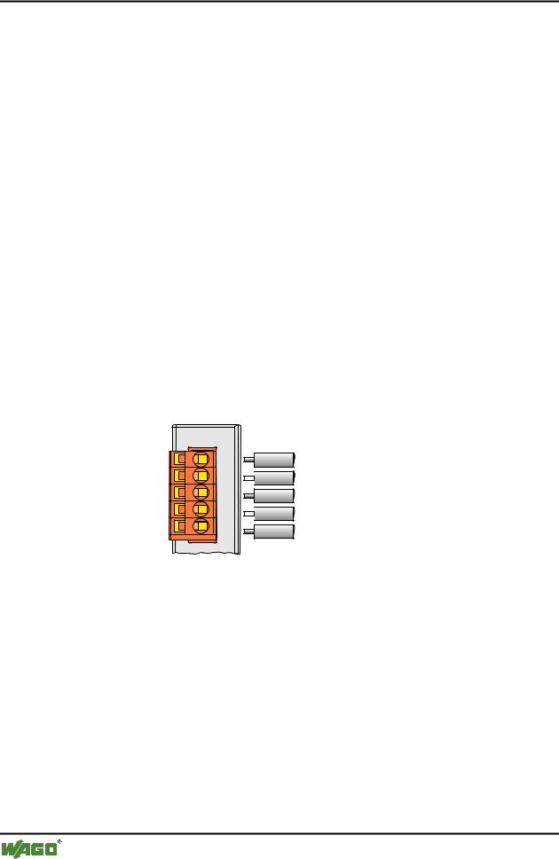
The connection of a WAGO fieldbus node to the DeviceNet bus cable is made by the supplied 5-pole plug (Multi Connector 231).
Fieldbus connection Series 231 (MCS)
V+
 CAN_High
drain

 CAN_Low
V-
Fig. 5-1: Plug assignment for the fieldbus connection
For wiring using a screened cable, the plus is assigned the connections V+, V- for the voltage supply and with CAN_High, CAN_Low for data transmission. The 24 V field bus supply is fed by an external fieldbus network power supply.
CAN_High and CAN_Low are two physically different bus levels. The cable screen is connected to the drain connection.
This is terminated with a 1 MΩ resistor to the DIN rail via the clip on the bottom of the Coupler/Controller. The DIN rail must then be directly connected to the Grounding Stud that must be connected to Earth Ground. We strongly recommend a central Earth Ground for the entire DeviceNet Bus conductor screening. A low Ohm connection of the screening on PE terminal can only be made externally.
WAGO-I/O-SYSTEM 750
DeviceNet
DeviceNet • 109
Network Architecture
Note
WAGO offers the screen connection system (series 790) for an optimum connection between fieldbus cable screening and functional earth.
Each DeviceNet node forms the differential voltage UDiff with: UDiff =
UCAN_High - UCAN_Low. using the bus levels CAN_High and CAN_Low. Differential signal transmission offers the advantage of an insensitivity com-
pared to common mode malfunctions and ground offset between the nodes.
Note
At its conductor ends, the bus cable must always be connected with a matching resistor of 120 Ohm to avoid reflections and, as a result, transmission problems.
This is also required for very short conductor lengths.
The CAN bus is a 2-wire bus and bus error management can detect a cable break or a short-circuit by the asymmetric operation.
Further information
The CiA provides documents regarding specifications, especially cable specifications on the Internet under:
http://www.can-cia.de
WAGO-I/O-SYSTEM 750
DeviceNet
110 • DeviceNet
Network Architecture
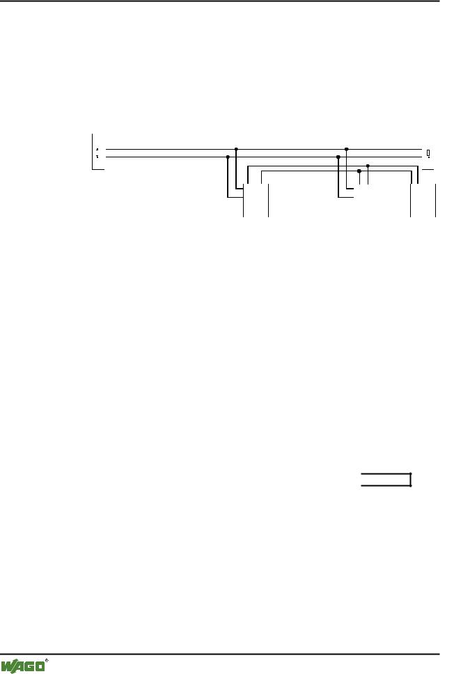
5.2.3 Network Topology
To build a simple DeviceNet network, you need a scanner (PC with a DeviceNet fieldbus PCB card), a connection cable and a DC 24 V power pack to ensure the power supply in addition to a DeviceNet fieldbus node.
The CANopen network is constructed as a line structure with matching resistors (120 Ohm).
Termination |
|
Termination |
120 |
|
120 |
WAGO |
Scanner |
Busnetz- |
I/O |
|
teil |
In systems accommodating more than two stations, all subscribers are wired in parallel. Node connection to the remote bus cable (trunk line) is made by means of drop lines. For this purpose, the bus cable has to be looped without interruption. A maximum length of 6 m for a drop line should not be exceeded.
The following is a topology example:

 Power Supply
WAGO-I/O-SYSTEM 750
DeviceNet