Материал: Стандарт MIL-STD-202G
MIL-STD-202G
Item |
Description |
Material |
Quantity 1/ |
|
|
|
|
1 |
Car building channel, 4 x 13.8 lb |
Steel |
1 |
2 |
Car building channel, 4 x 13.8 lb |
Steel |
1 |
3 |
Auxiliary mounting plate, .38 |
Steel |
1 |
4 |
Horizontal mounting plate, .50 |
Steel |
1 |
5 |
Hex head bolt, .750-10UNC-2A x 7.00 lg |
Steel (heat-treated) |
6 |
6 |
Hex head nut, .750-10UNC-2B |
Steel (heat treated) |
6 |
7 |
Washer, 2.00 OD x .18 ID |
Steel |
12 |
8 |
Pipe spacer, 1.00 standard, 2.81 lg |
Steel |
6 |
9 |
Gusset plate, .38 |
Steel |
2 |
10 |
Gusset plate, .38 |
Steel |
2 |
11 |
Gusset plate, .38 |
Steel |
2 |
12 |
Horizontal mounting plate, .50 |
Steel |
1 |
13 |
Horizontal mounting plate, .50 |
Steel |
1 |
14 |
Stiffener, .38 |
Steel |
4 |
15 |
Auxiliary mounting plate, .38 |
Steel |
1 |
16 |
Auxiliary mounting plate, .38 |
Steel |
1 |
|
|
|
|
1/ Quantities are for three mountings.
Inches |
mm |
Inches |
mm |
Inches |
mm |
Inches |
mm |
.18 |
4.57 |
1.25 |
31.75 |
9.00 |
228.60 |
20.00 |
508.00 |
.25 |
6.35 |
1.50 |
38.10 |
11.00 |
279.60 |
24.00 |
609.60 |
.38 |
9.65 |
2.00 |
50.80 |
12.00 |
304.80 |
26.50 |
647.70 |
.50 |
12.70 |
2.50 |
63.50 |
12.38 |
314.45 |
27.00 |
685.80 |
.62 |
15.75 |
2.81 |
71.73 |
13.00 |
330.20 |
27.75 |
704.85 |
.81 |
20.57 |
3.00 |
76.20 |
15.00 |
381.00 |
|
|
1.00 |
25.40 |
7.00 |
177.80 |
16.00 |
406.40 |
|
|
NOTES:
1.Unless otherwise specified, tolerance is ±.06 (1.52 mm).
2.Mounting platform number 3 shall be similar to mounting platform number 2 with the exception of the horizontal mounting plate and the side gusset plates shall be increased to 22.00 inches (558.80 mm).
3.The smallest mounting platform which will satisfactorily accommodate the specimen shall be selected.
4.If the deep gussets interfere with the mounted specimen, the extra bolt holes shall be used in bolting of mounting platform number 1 in the inverted position to the four lower bolt holes of the anvil plate.
FIGURE 207-6. Standard mounting-fixtures for deck or platform mounted parts - Continued.
METHOD 207B
8 February 2002
15
MIL-STD-202G
4. PROCEDURE.
4.1Mounting method. The specimens shall be installed by their normal mounting means on the mounting fixture in their normal operating position. Bolts for mounting the parts shall conform to type I, type II, or type III, grade 2, of MIL-DTL-1222, Studs, Bolts, Hex Cap Screws, Socket Head Cap Screws and Nuts. Mounting bolts shall be checked for tightness before each blow. Care shall be taken in the mounting procedure to prevent initial stresses being applied to the specimens prior to shock.
4.2Anvil-plate bolts and positioning springs. Due to the severity of the shock applied to the anvil plate by a series of three blows, the anvil-plate bolts shall be checked for tightness before each series of blows. The spacing between stops of the positioning springs (1.5 inches) shall also be corrected before each succession of blows.
4.3Direction of shock. A total of nine blows, three through each of the three principal mutually perpendicular axes for the heights indicated in 4.4, shall be delivered to the anvil plate supporting the specimens under test. Direction of the shock shall be, in order, to the back, top, and side. Back and top blows shall be applied with the anvil plate located to receive blows from the horizontal and vertical hammers. Side blows are delivered by the horizontal hammer contacting the end shock pad of the anvil plate (see 3.1).
4.4Height of hammer drops. The hammer shall strike the shock pad on the anvil plate, in sequence, from heights of 1 foot, 3 feet, and 5 feet.
4.5Hammer supports. During the test, the hammer not in use shall be disengaged from the lifting cable and supported so that the hammer and its support are not in contact with the anvil plate.
4.6Electrical load and operating conditions. The electrical load and operating conditions applied to the specimens shall be as specified.
4.7External resilient mountings. Unless otherwise specified, no external resilient mountings associated with the specimen being tested shall be used. Integral mounting devices and external resilient mountings (if specified) associated with the specimen shall remain unblocked during tests.
5.MEASUREMENTS. Monitoring of the specimens during test (e.g., delayed contact opening of relays, momentary stopping of dynamotors, calibration errors in meters) shall be as specified. Upon completion of the required number of blows, electrical and physical measurements shall be made as specified. Allowable tolerances shall be as specified.
6.SUMMARY. The following details are to be specified in the individual specification:
a.Mounting fixtures (see 3.3).
b.Electrical load on operating conditions, if applicable (see 4.6).
c.External resilient mountings, if required (see 4.7).
d.Monitoring during test, measurements after test, and allowable tolerances, as applicable (see 5).
METHOD 207B
8 February 2002
16
MIL-STD-202G
METHOD 208H
SOLDERABILITY
1.PURPOSE. The purpose of this test method is to determine the solderability of all terminations which are normally joined by a soldering operation. This determination is made on the basis of the ability of these terminations to be wetted by solder and the predictability of a suitable fillet resulting from solder application. These procedures will verify that the pre-assembly lead finish provides a solderable surface of sufficient quality to enable satisfactory soldering.
2.PROCEDURE. The solderability test shall be performed in accordance with ANSI/J-STD-002 “Solderabiilty Tests for Component Leads, Terminations, Lugs, Terminals and Wires” and herein. The following details and exceptions shall apply:
2.1Contractual agreements. The contractual agreements statement in ANSI/J-STD-002 shall not apply. Any exceptions to the requirements specified in ANSI/J-STD-002 and this test method shall be documented in the individual military procurement document or approved by the procuring military activity.
2.2Coating durability. The coating durability category (from ANSI/J-STD-002) shall be as follows:
a.Category 2 - for stranded wire (1 hour ±5 minutes steam aging with insulation removed).
b.Category 3 - for all other components (8 hours ±15 minutes steam aging).
2.3Test method. The test method used (from ANSI/J-STD-002) shall be as follows:
a.Test A - for through-hole mount and surface mount leaded components, solid wire less than .045 inch
diameter and stranded wire 18 AWG or smaller. If not otherwise specified in the procurement document, angle of immersion for surface mount leaded components shall be 90°.
b.Test B - for surface mount leadless components.
c.Test C - for lugs, tabs, terminals, solid wire greater than .045 inch diameter and stranded wire larger than 18 AWG.
3. SOLDERING IRON TEST METHOD. When specified in the individual specification, the soldering iron test method shall be performed as specified herein.
3.1Apparatus. The soldering iron used shall be temperature controlled and shall be capable of maintaining the measured idling tip temperature within ±5.5°C. Three-wire cords and tip grounding shall be used. The solder iron shall be of such design as to provide zero voltage switching. Solder guns of the transformer type shall not be used.
3.2Materials. The solder shall be composition Sn60Pb40A or Sn63Pb37A of ANSI/J-006 “Requirements for Electronic Grade Solder Alloys and Fluxed and Non-Fluxed Solid Solders for Electronic Soldering Applications”. The solder shall be of form W, flux symbol A, flux percentage symbol 6 or 7 (see ANSI/J-STD-006).
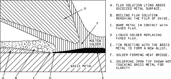
3.3Procedure. Preparation of terminations and aging shall be as specified in ANSI/J-STD-002 and 2.2 above. Flux shall be applied by a suitable method (e.g., brush) and allowed to drain for 5 to 20 seconds. Solder in accordance with 3.2 shall be applied to the terminal along with the clean solder coated tip of an iron (unless otherwise specified in the individual specification, iron temperature shall be 350°C) to a point ¼ inch from the nearest insulating material or ½ the exposed length of the terminal, whichever is closer. The termination shall be positioned so that the iron can be applied to the test surface in a horizontal position as in figure 208-1. Unless otherwise specified in the individual specification, the iron shall be applied for a period of 5 ±0.5 seconds and shall remain stationary during this period. Only enough solder shall be applied to flow a single thin layer of new solder.
METHOD 208H
31 January 1996
1 of 2
MIL-STD-202G
Should mechanical support for the termination be required while performing this test, such support shall be of thermally insulating material. For solder cups, the cup shall be filled with solder in accordance with 3.2, and the excess solder wicked out with a compatible fluxed solder wick. Prior to examination, flux residue shall be removed from the terminations by cleaning in a suitable solvent. Terminations shall be examined as specified in ANSI/J-STD-002.
4.SUMMARY. The following details shall be specified in the applicable procurement document.
a.Depth of immersion if other than specified.
b.Angle of immersion for surface mount leaded components, if other than 90°.
c.Measurements after test, when applicable.
d.Whether soldering iron method is to be used.
1.Soldering iron temperature if other than 350°C.
2.Duration of application of soldering iron if other than 5 ±0.5 seconds.
FIGURE 208-1. Soldering iron position and process diagram.
METHOD 208H
31 January 1996
2
MIL-STD-202G
METHOD 209
RADIOGRAPHIC INSPECTION
1. PURPOSE. Radiographic inspection is generally a nondestructive (see 1.1) method for detecting internal physical defects in small component parts which are not otherwise visible. Radiographic techniques are intended to reveal such flaws as improper positioning of elements, voids in encapsulating or potting compounds, inhomogeneities in materials, presence of foreign materials, broken elements, etc.
1.1 Precautions. Radiographic inspection may be performed on most parts; however, radiation may cause changes in electrical behavior of some materials.
2. APPARATUS AND MATERIALS.
2.1Radiographic equipment. The radiographic equipment used shall be capable of producing the required radiographic quality as specified in the individual specification. When using X-ray equipment, X-ray tubes with small effective focal-spot sizes and low inherent filtration are recommended.
2.2Film holder. A lightproof film holder of low inherent filtration to radiation is recommended when using voltages of 50 kilovolts. A lead backing plate should be used behind the film holder to minimize fogging due to secondary back-scatter.
2.3Image-quality indicator. The image-quality indicators used to indicate radiographic sensitivity shall be as specified in the individual specification. The sensitivity is the combined measure of the definition and contrast of the radiograph and should be such that the maximum allowable defect shall be shown. The image-quality indicator may be made from a sample part of the same type as the part being radiographed and should contain either an actual or simulated defect which is at least 10 percent smaller than the smallest defect to be detected.
2.4Film. The film shall be compatible with the sensitivity required in 2.1. In general, finer detail is achieved by the use of finer grain films with lower exposure indexes. If extreme magnification techniques are required, the use of single emulsion films is recommended.
2.5Nonfilm techniques. Nonfilm techniques may be used if required sensitivity levels, and records (when specified) can be obtained (see 2.1).
2.6Personnel safety precautions. The safety precautions described in National Bureau of Standards (NBS) Handbook 76 - X-Ray Protection; NBS Handbook 73 - Protection Against Radiations From Sealed Gamma Sources; Atomic Energy Commission Book Title 10, Part 20 - Standard for Protection Against Radiation, Part 30 - Licensing of By-product Material, Part 31 - Radiation Safety Requirements for Radiographic Operations, shall be complied with when applicable.
3. PROCEDURE.
3.1 Positioning of specimen. The leaded film holder is backed up by the lead plate (see 2.2), and the specimen to be radiographed shall be placed in the position or positions specified in the individual specification.
METHOD 209
18 May 1962
1 of 3