Материал: Стандарт MIL-STD-202G
MIL-STD-202G
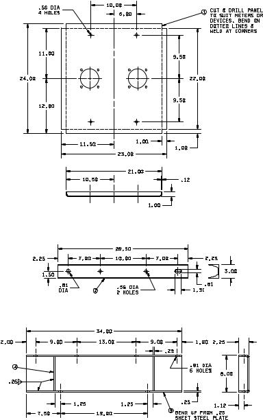
FIGURE 207-4A. Standard mounting fixtures for electrical-indicating switchboard meters and other panel-mounted parts.
METHOD 207B
8 February 2002
5
MIL-STD-202G
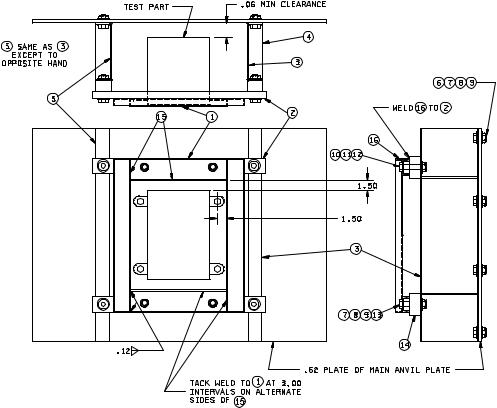
FIGURE 207-4A. Standard mounting fixtures for electrical-indicating switchboard meters and other panel-mounted parts - Continued.
METHOD 207B
8 February 2002
6
MIL-STD-202G
Item |
Description |
Material |
Quantity 1/ |
|
|
|
|
1 |
Panel |
Steel |
1 |
2 |
Standard channel, 3 x 5 pound |
Steel |
2 |
3 |
Fabricated spacer |
Steel |
1 |
4 |
Spacer stiffener |
Steel |
4 |
5 |
Fabricated spacer |
Steel |
1 |
6 |
Hex head bolt, .750-10UNC-2A x 1.75 lg |
Steel |
1 |
7 |
Hex head nut, .750-10UNC-2B |
Steel |
12 |
8 |
Washer, 2.00 OD x .81 ID |
Steel |
12 |
9 |
Washer, 1.38 OD x .81 ID |
Steel |
12 |
10 |
Hex head bolt, .500-13UNC-2A x 1.00 lg |
Steel |
4 |
11 |
Hex head nut, .500-13UNC-2B |
Steel |
4 |
12 |
Washer, 1.38 OD x .56 ID |
Steel |
4 |
13 |
Hex head bolt, .750-10UNC-2A x 2.50 lg |
Steel |
4 |
14 |
Block, 2.25 x 2.00 x 1.25 |
Steel |
4 |
|
|
|
|
1/ Quantities are for one mounting.
Inches |
mm |
Inches |
mm |
Inches |
mm |
Inches |
mm |
.06 |
1.52 |
1.31 |
33.27 |
7.00 |
177.80 |
12.00 |
304.80 |
.12 |
3.05 |
1.38 |
35.05 |
7.50 |
190.50 |
13.00 |
330.20 |
.25 |
6.35 |
1.50 |
38.10 |
8.00 |
203.20 |
19.00 |
482.60 |
.56 |
14.22 |
1.75 |
44.45 |
9.00 |
228.60 |
21.00 |
533.40 |
.62 |
15.75 |
2.00 |
50.80 |
9.50 |
241.30 |
22.00 |
558.80 |
.81 |
20.57 |
2.25 |
57.15 |
10.00 |
254.00 |
23.00 |
584.20 |
1.00 |
25.40 |
2.50 |
63.50 |
10.50 |
266.70 |
24.00 |
609.60 |
1.12 |
28.45 |
3.00 |
76.20 |
11.00 |
279.40 |
28.50 |
722.90 |
1.25 |
31.75 |
5.00 |
127.00 |
11.50 |
292.10 |
34.00 |
863.60 |
NOTES:
1.Unless otherwise specified, tolerance is ±.06 (1.52 mm).
2.Two identical specimens shall be mounted on the panel provided there is a minimum separation of 3.00 inches (76.20 mm) when the indicated 10.00 inches (254.00 mm) centers are used (total weight not to exceed 40 pounds).
3.In the event that the requirement of note 2 can be met, but is desired to test only one specimen, a counterbalance of approximately the same weight shall be mounted in a corresponding position on the opposite side of the panel. Mounting dimensions for the counterbalance shall be the same as for the specimen.
4.In the event that the requirement of note 2 cannot be met, the specimen shall be mounted centrally on the panel; if the individual specimen weight is in excess of 20 pounds, the panel shall be reinforced as indicated on figure 207-4B.
5.Specimens too large to be tested on this panel shall utilize the panel indicated on figure 207-4B.
6.If the depth of the specimen is such that the minimum clearance of 1.00 inch (25.40 mm) cannot be maintained, the specimen shall be turned around so that the front faces the anvil plate.
FIGURE 207-4A. Standard mounting fixtures for electrical-indicating switchboard meters and other panel-mounted parts - Continued.
METHOD 207B
8 February 2002
7
MIL-STD-202G
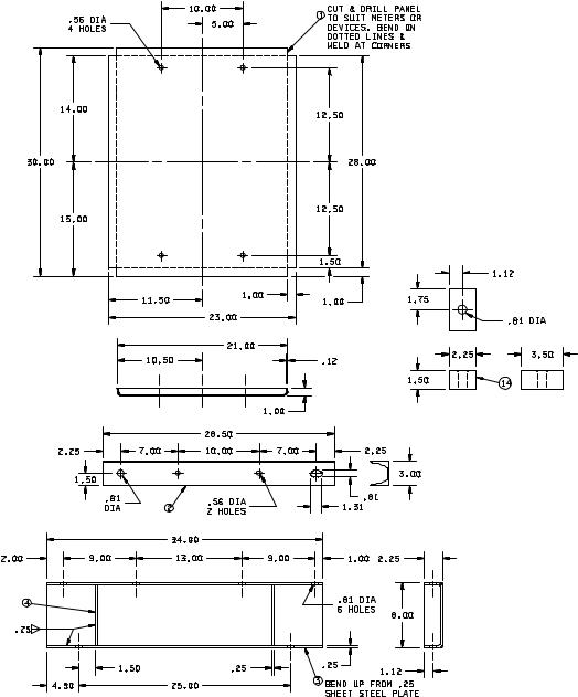
FIGURE 207-4B. Standard mounting fixtures for electrical-indicating switchboard meters and other panel-mounted parts.
METHOD 207B
8 February 2002
8
MIL-STD-202G
FIGURE 207-4B. Standard mounting fixtures for electrical-indicating switchboard meters and other panel-mounted parts - Continued.
METHOD 207B
8 February 2002
9