Материал: Стандарт MIL-STD-202G
MIL-STD-202G
Resistors
R1 - 35K 1/2W, 1% (see note 1) R2 - 27K 1/2W, 5%
R3 - 47K 1W, 5% R4 - 200K 1/2W, 5% R5 - 70K 1W, 5% R6 - 2.4K 1W, 5% R7 - 5K 1W
R8 - 500 1/2W, 5%
Capacitors
C1 - .0022 F, 600 VDCW (see note 1)
Miscellaneous
DS1 |
- NE-51 |
S1 |
- DPDT |
S2 |
- SPSTNC 125V 1 amp (push) |
V1 |
- JAN-5727/2D21W |
NOTES:
1.These values are to be chosen to obtain the desired time-duration for the applicable test condition (see 4.3). These particular values are applicable to 10 microseconds time-duration only.
FIGURE 310-1. Test-circuit A; monitor circuit for contact-opening and closing.
METHOD 310
20 January 1967
3
METHOD 310
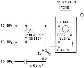
NOTE: The oscilloscope shall have an accuracy of ±3 percent or better on time base and have provision for external triggering.
FIGURE 310-2. Calibration circuit for test-circuit A.
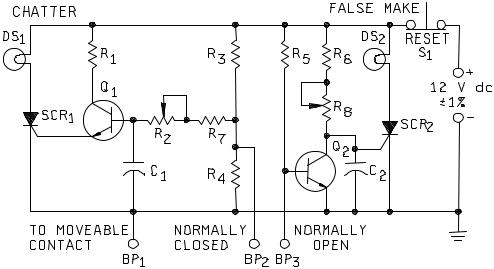
3.2 Test circuit B. The monitor-circuit shown on figure 310-3 permits detection of contact-chatter of closed contacts and false closure of open contacts, independently or simultaneously. The low contact-load levels (see 2.1.2) insure that there will be no arcing of the contacts during monitoring.
a.The chatter portion of figure 310-3, resistors R3 and R4 form a voltage divider with their junction at +2 volts. The closed contacts of the component under test, short-circuit R4 and place the base of transistor amplifier Q1 to ground potential. When the contacts under test "chatter" (open), resistor R4 is no longer shortcircuited and capacitor C1 starts to charge through R2 and R7 to +2 volts. The time necessary for C1 to charge to the correct bias-level is determined by the resistance of R2 and R7 and the capacitance value of C1. As transistor Q1 draws current through the gate of SCR1, the unit will fire and turn-on lamp DS1. Since in a silicon-controlled rectifier, the gate loses control after it is turned "on", the contacts can reclose at any
time thereafter without affecting the monitoring circuit. The time-delay, before turn-on, can be adjusted by varying R2 and selecting the capacitance value of C1. (For example: C1 = .002 F gives a 10-microsecond open-contact time.)
b.In the false-make portion of figure 310-3, transistor-amplifier Q2 is normally "on" with the gate of SCR2 being effectively held at ground potential by the low-output impedance of transistor Q2. When a "false-make" occurs, the base of Q2 transistor is grounded, turning Q2 "off". This allows the gate of the SCR2, which is
tied to the collector of transistor Q2, to rise to +12 volts. The rate of increase is determined by the value of C2 and R8. (For example: C2 = .002 F gives a 10-microsecond false-make time.) When the voltage reaches the gate turn-on level of SCR2, lamp DS2 will light, indicating a false closure of the open contacts.
METHOD 310
20 January 1967
4
MIL-STD-202G
c.When this circuit is being used to simultaneously monitor both the open and closed contacts of a double set of contacts:
(1)If DS1 "lights", it is an indication of contact chatter.
(2)If DS1 and DS2 "lights", it is an indication of false transfer or possible bridging, i.e., the movable contact of the open circuit "closes" but the closed circuit has not opened.
(3)If DS2 "lights", it is an indication of bridging.
d.Restoration of the circuit for an indication of failure is accomplished by the operation of S1.
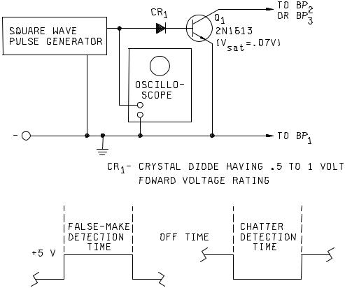
3.2.1 Calibration procedure for test-circuit B. The calibration-circuit shown on figure 310-4 may be used to calibrate the monitoring-circuit shown on figure 310-3 by using the following procedure:
a.Make the proper connections of the monitoring-circuit to the calibration-circuit.
(1)BP1 and BP2 for contact-chatter calibration.
(2)BP1 and BP3 for false contact-make calibration.
b.Select the appropriate 5 volt square-wave "pulse-polarity" and "pulse-width" to be furnished by the pulse generator and monitor the pulse on the oscilloscope, as follows:
(1)For contact-chatter calibration: Negative pulse.
(2)For false contact-make calibration: Positive pulse.
(3)Pulse width for either of the preceding (1) or (2) equal to the required detection time.
c.If DS1 or DS2 (as applicable) "lights", adjust R2 or R8 until the light is extinguished.
d.Slowly adjust R2 and R8 (as applicable) to the time-duration specified in the individual specification, as indicated by the first point at which DS1 or DS2 "lights".
METHOD 310
20 January 1967
5
MIL-STD-202G
C1, C2 |
- Choose for specified time (see note 1) |
R6 |
- 1,000 ohms 1/4W, 5% |
DS1, DS2 |
- No. 344 Lamp |
R7 - 100 ohms 1/4W, 5% |
|
R1 - 750 ohms 1/4W, 5% |
R8 |
- 200 ohms pot. |
|
R2 |
- 2,000 ohms pot. |
Q1, Q2 |
- 2N332A or equivalent |
R3, R5 |
- 10,000 ohms 1/4W, 5% |
SCR1, SCR2 |
- 2N1595 or equivalent |
R4 |
- 2,500 ohms 1/4W, 5% |
S1 |
- SPST NC Push |
NOTE:
1.Use .0022 F for 10 microsecond time-duration. Other time-duration will require larger capacitors.
FIGURE 310-3. Test-circuit B; monitor circuit for contact-chatter and false closures.
METHOD 310
20 January 1967
6
MIL-STD-202G
NOTES:
1.The square-wave pulse generator and oscilloscope shall have an accuracy of ±3 percent or better.
2.The ratio of off-time to detection-time shall be 10:1 or better.
FIGURE 310-4. Calibration circuit for test-circuit B.
METHOD 310
20 January 1967
7