Материал: Стандарт MIL-STD-202G
MIL-STD-202G
NOTE: Metric equivalents are in parentheses.
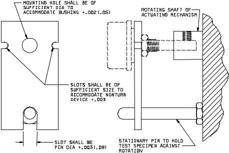
FIGURE 206-1. Suggested mounting fixture for rotational-life test.
2.6 Temperature and atmospheric pressure. When specified, this test shall be performed at elevated or reduced temperature and at other than room ambient atmospheric pressure.
3.MEASUREMENTS. Specified measurements or tests shall be made prior to, during, or after rotations, as specified.
4.SUMMARY. The following details are to be specified in the individual specification:
a.Spacing of specimens for elevated-temperature testing, when applicable (see 2.1).
b.Test potential and load (see 2.2).
c.Cycle, if other than specified (see 2.3).
d.Cycle rate in cpm (see 2.4).
e.Test condition letter (see 2.5).
f.Temperature and atmospheric conditions, when applicable (see 2.6).
g.Measurements or tests prior to, during, or after rotations, as applicable (see 3).
METHOD 206
12 September 1963
2
MIL-STD-202G
METHOD 207B
HIGH-IMPACT SHOCK
1.PURPOSE. This test is performed for the purpose of determining the ability of various parts to withstand shock of the same severity as that produced by underwater explosions, collision impacts, near-miss gunfire, blasts caused by air explosions, and field conditions. Exact simulation of some of the severe shock motions experienced in the field is difficult to reproduce; however, parts that successfully complete the test of this method have been found to possess the necessary ruggedness for this use. The test apparatus utilized in this method is the same as that designated as Shock Testing Machine for Lightweight Equipment in MIL-S-901, Shock Tests, HI (High-Impact), Shipboard Machinery, Equipment and Systems, Requirements for. The purpose of this apparatus is to determine the ability of equipment installed aboard naval ships to withstand shock and still continue to perform its operational function. This test method is limited to testing of parts weighing not more than 300 pounds.
2.PRECAUTIONS. The apparatus shall be examined periodically for damage. Any hardware that has become defective by being deformed or cracked shall be replaced. Particular attention shall be given to the anvil plate which shall not be bowed more than 1 inch at the center. Proper safeguards shall be taken to protect personnel from objects that may become loosened and act as projectiles as a result of this test. A sound-warning arrangement shall be made, for use in alerting personnel in the vicinity of the test of the impending drop of the hammer.
3.APPARATUS. The apparatus used in this test method shall be as shown on figure 207-1 and the associated detail drawings. The parts shall be installed on a mounting fixture which is attached to the anvil plate of the shocktesting apparatus. A 400-pound hammer shall be dropped from a specified height (see 4.4) onto a shock pad located on the anvil plate. The shock motion is then transmitted by the anvil plate to the parts attached on the mounting fixture.
3.1Anvil plate. The test apparatus of this method is so constructed that the anvil plate (see figure 207-3) can be installed, in sequence, in two positions. By utilizing these two installation positions and separately employing both hammers of the apparatus shock is applied through the three principal mutually perpendicular axes of the part being subjected to test. One position is to locate the anvil in such a manner that it will receive blows through the back of the anvil plate by contact from the horizontal hammer, and blows on the top shock pad of the anvil plate by a drop of the vertical hammer as shown on figure 207-2. The other position is as shown on figure 207-1, whereby the end shock pad is contacted by the horizontal hammer.
3.2Hammers. The test apparatus is equipped with two 400-pound hammers. One hammer renders a blow by a vertical drop. The other hammer applies a force in a horizontal direction. In this manner, and by changing the orientation of the anvil plate, blows may be delivered to the anvil and the parts in three directions.
3.3Mounting fixtures. Figure 207-4A, figure 207-4B, figure 207-5, and figure 207-6 show standard mounting fixtures that shall be used when testing parts with this test apparatus. These mounting fixtures simulate platform and panel mountings. The applicable mounting fixture shall be as specified. When one of the standard mounting fixtures shown on figure 207-4A, figure 207-4B, figure 207-5, and figure 207-6 cannot be used, the individual specification shall specify a mounting fixture or adapter which approximates the actual rigidity encountered in service.
METHOD 207B
8 February 2002
1 of 16
MIL-STD-202G
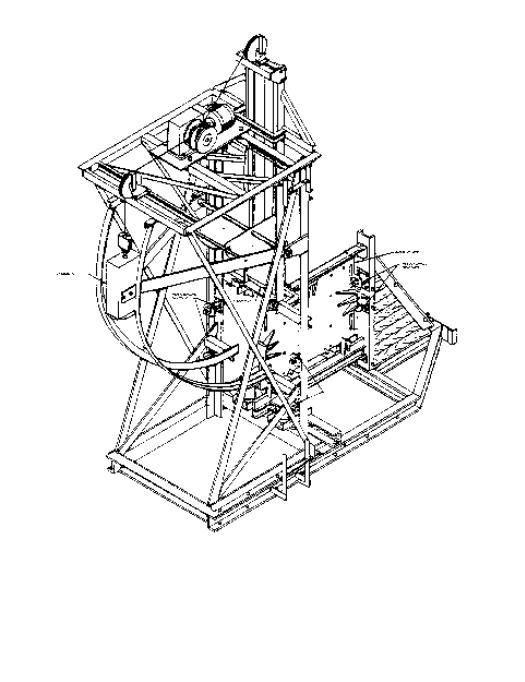
FIGURE 207-1. High-impact shock-testing apparatus.
METHOD 207B
8 February 2002
2
MIL-STD-202G
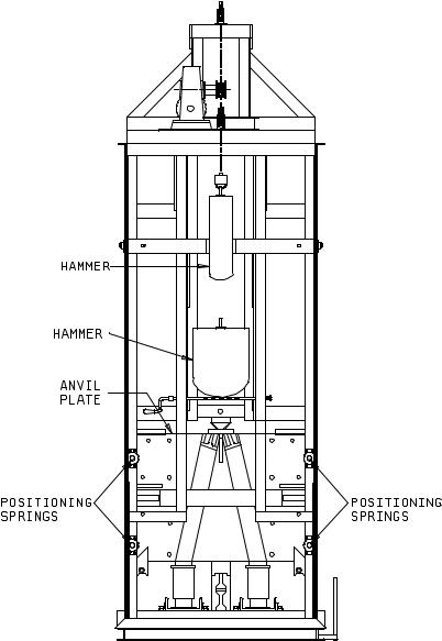
FIGURE 207-2. High-impact shock-testing apparatus (backview) with anvil plate located for back and top blows.
METHOD 207B
8 February 2002
3
MIL-STD-202G
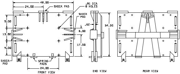
Inches |
mm |
Inches |
mm |
.62 |
15.75 |
17.00 |
431.80 |
.81 |
20.57 |
24.00 |
609.60 |
6.00 |
152.40 |
34.00 |
863.60 |
9.00 |
228.60 |
48.00 |
1,219.20 |
13.00330.20
NOTE: Unless otherwise specified, tolerances are ±.06 (1.52 mm).
FIGURE 207-3. Anvil plate of shock-testing apparatus.
METHOD 207B
8 February 2002
4