Материал: Стандарт MIL-STD-202G
MIL-STD-202G
Item |
Description |
Material |
Quantity 1/ |
|
|
|
|
1 |
Panel |
Steel |
1 |
2 |
Standard channel, 3 x 5 pound |
Steel |
2 |
3 |
Fabricated spacer |
Steel |
1 |
4 |
Spacer stiffener |
Steel |
4 |
5 |
Fabricated spacer |
Steel |
1 |
6 |
Hex head bolt, .750-10UNC-2A x .75 lg |
Steel |
8 |
7 |
Hex head nut, .750-10UNC-2B |
Steel |
12 |
8 |
Washer, 2.00 OD x .18 ID |
Steel |
12 |
9 |
Washer, 1.38 OD x .18 ID |
Steel |
12 |
10 |
Hex head bolt, .500-13UNC-2A x 1.00 lg |
Steel |
4 |
11 |
Hex head nut, .500-13UNC-2B |
Steel |
4 |
12 |
Washer, 1.38 OD x .56 ID |
Steel |
4 |
13 |
Hex head bolt, .750-10UNC-2A x 4.00 lg |
Steel |
4 |
14 |
Spacer block |
Steel |
4 |
15 |
Strap, .12 x 1.00 |
Steel |
4 |
16 |
Block, 2.25 x 21.25 |
Steel |
4 |
|
|
|
|
1/ Quantities are for one mounting.
Inches |
mm |
Inches |
mm |
Inches |
mm |
Inches |
mm |
.06 |
1.52 |
1.12 |
28.45 |
4.00 |
101.60 |
12.50 |
317.50 |
.12 |
3.05 |
1.31 |
33.27 |
4.50 |
114.30 |
13.00 |
330.20 |
.18 |
4.57 |
1.38 |
35.05 |
5.00 |
127.00 |
14.00 |
355.60 |
.25 |
6.35 |
1.50 |
38.10 |
7.00 |
177.80 |
15.00 |
381.00 |
.56 |
14.22 |
1.75 |
44.45 |
8.00 |
203.20 |
21.00 |
533.40 |
.62 |
15.75 |
2.00 |
50.80 |
9.00 |
228.60 |
21.25 |
539.75 |
.75 |
19.05 |
2.25 |
57.15 |
10.00 |
254.00 |
23.00 |
584.20 |
.81 |
20.57 |
3.00 |
76.20 |
10.50 |
266.70 |
25.00 |
635.00 |
1.00 |
25.40 |
3.50 |
88.90 |
11.50 |
292.10 |
28.00 |
710.20 |
|
|
|
|
|
|
30.00 |
762.00 |
|
|
|
|
|
|
34.00 |
863.60 |
NOTES:
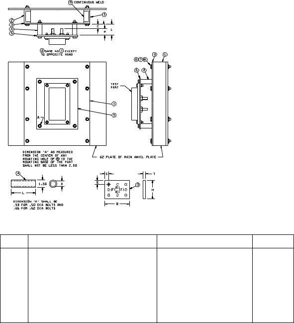
1.Unless otherwise specified, tolerance is ±.06 (1.52 mm).
2.This panel shall not be used if the panel indicated on figure 207-4A is applicable.
3.The spacer blocks, item 14, shall be used only when necessary to maintain a minimum clearance of 1.00 inch (25.40 mm) between the specimen and the anvil plate.
4.In the event that the depth of the specimen is such that the minimum clearance of 1.00 inch (25.40 mm) cannot be maintained, the spacer blocks shall be removed and the specimen mounted with the front surface toward the anvil plate.
FIGURE 207-4B. Standard mounting fixtures for electrical-indicating switchboard meters and other panel-mounted parts - Continued.
METHOD 207B
8 February 2002
10
MIL-STD-202G
|
|
Inches |
mm |
|
|
.18 |
4.57 |
|
|
.50 |
12.70 |
|
|
.53 |
13.46 |
|
|
.62 |
15.75 |
|
|
.66 |
16.76 |
|
|
1.00 |
25.40 |
|
|
1.50 |
38.10 |
|
|
1.94 |
49.28 |
|
|
2.00 |
50.80 |
|
|
2.50 |
63.50 |
|
|
7.00 |
177.80 |
|
|
27.00 |
685.80 |
|
|
34.00 |
863.60 |
|
|
36.00 |
914.40 |
Item |
Description |
Material |
Quantity 1/ |
1 |
Car building channel, 4 x 13.8 pounds |
Steel |
1 |
2 |
Car building channel, 4 x 13.8 pounds |
Steel |
1 |
2/ 3 |
Auxiliary mounting plate, .50 x 27.00 x 34.00 |
Steel |
1 |
4 |
Spacer (see table 1) |
Steel |
|
5 |
Plastic mounting panel (see table 2) |
Plastic, laminated, type FBG, in |
|
6 |
Hex head bolt; .750-10UNC-2A x 7.00 lg |
accordance with MIL-I-24768/14 |
|
Steel (heat-treated) |
8 |
||
7 |
Hex head nut, .750-10UNC-2B |
Steel |
8 |
8 |
Washer, 2.00 OD x .18 ID |
Steel |
16 |
9 |
Pipe spacer, 1.00 standard, 1.94 lg |
Steel |
8 |
1/ Quantities are for one mounting.
2/ The size of the auxiliary mounting plate shall be increased to .50 x 36.00 x 34.00 for panels No. 5 and No. 6 listed in table II.
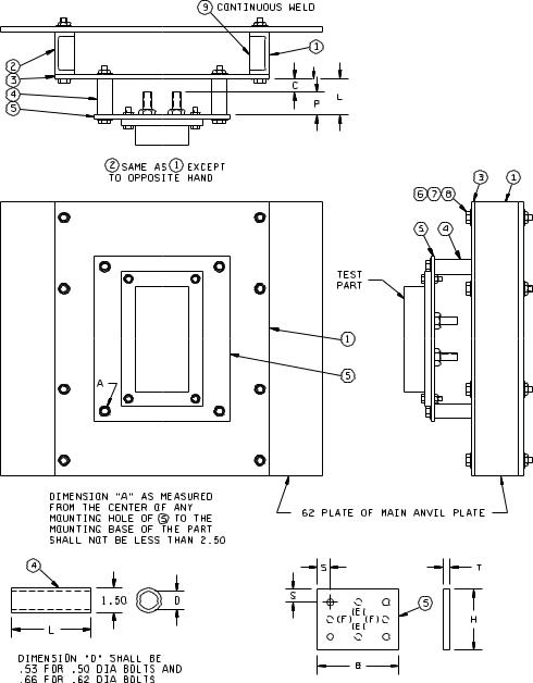
FIGURE 207-5. Standard mounting fixtures for electrical controller parts (contractors, relays, resistors, etc.).
METHOD 207B
8 February 2002
11
MIL-STD-202G
Holes (E) are drilled equidistant from corner holes on same center line - panels No. 5 and No. 6 only. Holes (F) are drilled equidistant from corner holes on same center line - panels No. 4 and No. 6 only.
TABLE I. Spacers.
When P (note assembly plan view) is: |
L |
Remarks |
|
|
|
|
|
Less than |
Greater than |
|
|
|
|
|
|
.75 |
|
1.50 |
|
(19.05) |
|
(38.10) |
|
3.25 |
.75 |
P + .75 |
|
(82.55) |
(19.05) |
|
|
|
3.25 |
4.00 |
Cut out .50 inch (12.70 mm) thick auxiliary mounting |
|
(82.55) |
(101.60) |
plate, item 3, to give .75 inch clearance around rear |
|
|
|
projections. |
|
|
|
|
Selection of panel size: The panel employed shall be the smallest size shown in the above table that will result in a clearance, "A" (note assembly front elevation view), of at least 2.50.
TABLE II. Mounting panels.
Panel |
B |
H |
T |
S |
Size of bolts |
Bolt-hole |
Quantity |
number |
|
|
|
|
|
diameter |
|
|
|
|
|
|
|
|
|
1 |
9.00 |
12.00 |
.75 |
1.00 |
.500-13UNC-2A |
.56 |
4 |
|
(228.60) |
(304.80) |
(19.05) |
(25.40) |
|
(14.22) |
|
2 |
12.00 |
16.00 |
1.00 |
1.00 |
.500-13UNC-2A |
.56 |
4 |
|
(304.80) |
(406.40) |
(25.40) |
(25.40) |
|
(14.22) |
|
3 |
16.00 |
20.00 |
1.00 |
1.00 |
.500-13UNC-2A |
.56 |
4 |
|
(406.40) |
(508.00) |
(25.40) |
(25.40) |
|
(14.22) |
|
4 |
20.00 |
24.00 |
1.00 |
1.00 |
.500-13UNC-2A |
.56 |
6 |
|
(508.00) |
(609.60) |
(25.40) |
(25.40) |
|
(14.22) |
|
5 |
32.00 |
24.00 |
1.00 |
1.25 |
.625-11UNC-2A |
.69 |
6 |
|
(812.80) |
(609.60) |
(25.40) |
(31.75) |
|
(17.53) |
|
6 |
36.00 |
34.00 |
1.00 |
1.25 |
.625-11UNC-2A |
.69 |
8 |
|
(914.40) |
(863.60) |
(25.40) |
(31.75) |
|
(17.53) |
|
|
|
|
|
|
|
|
|
NOTES:
1.Metric equivalents are in parentheses.
2.Unless otherwise specified, tolerances are ±.06 inch (1.52 mm).
FIGURE 207-5. Standard mounting fixtures for electrical controller parts (contractors, relays, resistors, etc.) - Continued.
METHOD 207B
8 February 2002
12
MIL-STD-202G
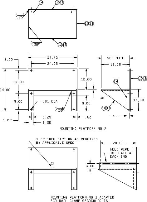
FIGURE 207-6. Standard mounting fixtures for deck, or platform, mounted parts.
METHOD 207B
8 February 2002
13
MIL-STD-202G
FIGURE 207-6. Standard mounting-fixtures for deck or platform mounted parts - Continued.
METHOD 207B
8 February 2002
14