Материал: part05
Page 126 DICOM PS3.5 2020a - Data Structures and Encoding
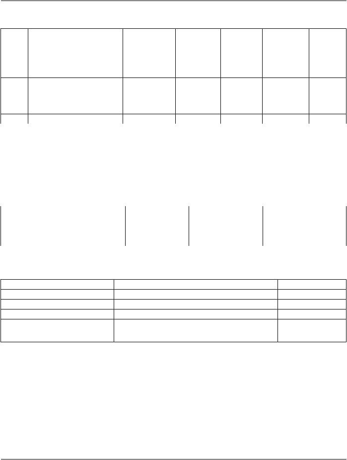
Table F.1-1. JPEG Modes of Image Coding
No. |
Description |
Lossy |
Non-Hierarchical |
Sequential |
Transform |
Coding |
Accepted |
|
|
LY |
NH |
S |
|
|
Bits |
|
|
|
|
|
|||
|
|
Lossless |
Hierarchical |
Progressive |
|
|
|
|
|
LL |
H |
P |
|
|
|
1 |
Baseline |
LY |
NH |
S |
DCT |
Huffman |
8 |
2 |
Extended |
LY |
NH |
S |
DCT |
Huffman |
8 |
4 |
Extended |
LY |
NH |
S |
DCT |
Huffman |
12 |
14 |
Lossless |
LL |
NH |
S |
DPCM |
Huffman |
2-16 |
The different coding processes specified in the JPEG Standard are closely related. By extending the capability of an implementation, increasingly more 'lower level' processes can also be executed by the implementation. This is shown in Table F.1-2 for Huffman Coding.
InclusionofaJPEG-codedimageinaDICOMmessageisfacilitatedbytheuseofspecificTransferSyntaxesthataredefinedinAnnex A. Independent of the JPEG coding processes, the same syntax applies. The only distinction for different processes in the syntax (apart from different SOF marker segments in the JPEG bit stream) is the UID value. Table F.1-5 lists the UID values in the Transfer Syntax for the various JPEG coding processes for reference.
Table F.1-2. Relationship Between the Lossy JPEG Huffman Coding Processes
Process |
1 |
2 |
4 |
1 |
* |
* |
* |
2 |
|
* |
* |
4 |
|
|
* |
* Coding process of column can execute coding process of row
Table F.1-5. Identification of JPEG Coding Processes in DICOM
DICOM Transfer Syntax UID |
JPEG process |
JPEG description |
capable of decoding |
1.2.840.10008.1.2.4.50 |
1 |
baseline |
1 |
1.2.840.10008.1.2.4.51 |
2,4 |
extended |
1,2,4 (see Note) |
1.2.840.10008.1.2.4.57 |
14 |
lossless NH |
14 |
1.2.840.10008.1.2.4.70 |
14 |
lossless NH, first-order prediction |
|
|
Selection Value 1 |
|
|
Note |
|
|
|
Though the coding processes (2, 4) described in ISO 10918-1 are capable of decoding the other listed process (1), the bit stream uses different SOF marker segments. I.e., the baseline JPEG process 1 used with the 1.2.840.10008.1.2.4.50 Transfer Syntax uses the SOF0 marker, whereas the extended process 2 used with the 1.2.840.10008.1.2.4.51 Transfer Syntax uses the SOF1 marker. Accordingly, even though both bit streams encode 8 bit images using DCT and Huffman coding, the bit streams are not identical.
ISO 10918-2 describes compliance tests for decoders, and requires that implementations of specific extended processes (such as 2 and 4) be capable of decoding bit streams of related baseline processes (such as 1) (ISO 10918-2 Section 7.4 Compliance tests for DCT-based sequential mode decoding processes). The converse is not true for encoders however, and the presence of SOF marker segments not defined by the specific process is not compliant (ISO 10918-2 Section 5.1.1 Non-hierarchical coding processes syntax compliance test Tables 1 and 2).
- Standard -

DICOM PS3.5 2020a - Data Structures and Encoding |
Page 127 |
F.2 Encapsulated JPEG-LS Encoded Images
TheInternationalStandardsOrganization(ISO/IECJTC1/SC2/WG10)haspreparedanInternationalStandard,ISO/IS-14495-1(JPEG- LS Part 1), for the digital compression and coding of continuous-tone still images. This standard is known as the JPEG-LS Standard.
Part 1 of the JPEG-LS Standard sets out requirements and implementation guidelines for the coded representation of compressed imagedatatobeinterchangedbetweenapplications.Theprocessesandrepresentationsareintendedtobegenericinordertosupport the broad range of applications for color and grayscale still images for the purpose of communications and storage within computer systems.
The JPEG-LS Standard specifies a single lossy (near-lossless) code process that can achieve lossless compression by constraining the absolute error value during encoding to zero. The lossless and lossy (near-lossless) coding is based on a predictive scheme with statistical modeling, in which differences between pixels and their surround are computed and their context modeled prior to coding, with a run-length escape mechanism. This scheme achieves consistently better compression in lossless mode than the lossless processes of JPEG defined in ISO 10918-1, with less complexity.
ThoughadifferentcodingprocessfromthosespecifiedinISO10918-1isused,thesyntaxoftheencodedbitstreamiscloselyrelated.
A single JPEG-LS process is used for bit depths up to 16 bits.
Inclusion of a JPEG-LS coded image in a DICOM message is facilitated by the use of specific Transfer Syntaxes that are defined in Annex A.
F.3 Encapsulated JPEG 2000 Encoded Images
TheInternationalStandardsOrganization(ISO/IECJTC1/SC2/WG10)haspreparedanInternationalStandard,ISO/IEC-15444(JPEG 2000), for the digital compression and coding of continuous-tone still images. This standard is known as the JPEG 2000 Standard.
The JPEG 2000 Standard sets out requirements and implementation guidelines for the coded representation of compressed image data to be interchanged between applications. The processes and representations are intended to be generic in order to support the broadrangeofapplicationsforcolorandgrayscalestillimagesforthepurposeofcommunicationsandstoragewithincomputersystems.
ThoughadifferentcodingprocessfromthosespecifiedinISO10918-1isused,thesyntaxoftheencodedbitstreamiscloselyrelated.
A single JPEG 2000 process is used for bit depths up to 16 bits.
Inclusion of a JPEG 2000 coded image in a DICOM message is facilitated by the use of specific Transfer Syntaxes that are defined in Annex A.
- Standard -

Page 128 |
DICOM PS3.5 2020a - Data Structures and Encoding |
- Standard -

DICOM PS3.5 2020a - Data Structures and Encoding |
Page 129 |
G Encapsulated RLE Compressed Images (Normative)
G.1 Summary
This annex describes how to apply RLE Image Compression to an image or an individual frame of a multi-frame image. This method can be used for any image, independent of the values of the data elements that describe the image (i.e., Photometric Interpretation (0028,0004) and Bits Stored (0028,0101)).
RLE Image Compression consists of the following steps:
1.The image is converted to a sequence of Composite Pixel Codes (see PS3.3).
2.The Composite Pixel Codes are used to generate a set of Byte Segments (see Section G.2).
3.Each Byte Segment is RLE compressed to produce a RLE Segment (see Section G.4).
4.The RLE Header is appended in front of the concatenated RLE Segments (see Section G.5).
G.2 Byte Segments
A Byte Segment is a series of bytes generated by decomposing the Composite Pixel Code (see PS3.3).
If the Composite Pixel Code is not an integral number of bytes in size, sufficient Most Significant zero bits are added to make it an integral byte size. This is known as the Padded Composite Pixel Code.
The first Segment is generated by stripping off the most significant byte of each Padded Composite Pixel Code and ordering these bytes sequentially. The second Segment is generated by repeating this process on the stripped Padded Composite Pixel Code con- tinuing until the last Pixel Segment is generated by ordering the least significant byte of each Padded Component Pixel Code sequen- tially.
Note
1.IfPhotometricInterpretation(0028,0004)equalsRGBandBitsAllocatedequals8,thenthreeSegmentsaregenerated. The first one holds all the Red values, the second all the Green values, and the third all the Blue values.
2.The use of separate segments implies that the Planar Configuration (0028,0006) could theoretically be 1 for RLE com- pressedimages,butforconsistencywithotherEncapsulated(compressed)TransferSyntaxesandrestrictionsonPlanar Configuration in many IODs, it may be 0 unless constrained by the IOD.
G.3 The RLE Algorithm
The RLE algorithm described in this section is used to compress Byte Segments into RLE Segments. There is a one-to-one corres- pondence between Byte Segments and RLE Segments. Each RLE segment must be an even number of bytes or padded at its end with zero to make it even.
G.3.1 The RLE Encoder
A stream of identical bytes (Replicate Run) is encoded as a two-byte code:
< -count + 1 > <byte value>, where
count = the number of bytes in the run, and
2 <= count <= 128
and a non-repetitive octet-stream (Literal Run) is encoded as:
- Standard -

Page 130 |
DICOM PS3.5 2020a - Data Structures and Encoding |
< count - 1 > <Literal octet-stream>, where
count = number of bytes in the octet-stream, and
1 <= count <= 128.
The value of -128 may not be used to prefix a byte value.
Note
It is common to encode a 2-byte repeat run as a Replicate Run except when preceded and followed by a Literal Run, in which case it's best to merge the three runs into a Literal Run.
Three-byte repeats shall be encoded as Replicate Runs. Each row of the image shall be encoded separately and not cross a row boundary.
G.3.2 The RLE Decoder
Pseudo code for the RLE decoder is shown below:
Loop until the number of output bytes equals the uncompressed segment size
Read the next source byte into n
If n> =0 and n <= 127 then
output the next n+1 bytes literally
Elseif n <= - 1 and n >= -127 then
output the next byte -n+1 times
Elseif n = - 128 then
output nothing
Endif
Endloop
G.4 Organization of RLE Compressed Frame
The RLE Segments are ordered as described in Section G.2. They are preceded by the RLE Header, which contains offsets to the start of each RLE Segment. The RLE Header is described in G.5.
The first RLE Segment immediately follows the RLE Header and the remaining RLE Segments immediately follow each other. This is illustrated in the diagram below.
Table G.4-1. Organization of RLE Compressed Frame
Header
RLE Segment 1
RLE Segment 2
. . .
. . .
RLE Segment n
- Standard -