Материал: part05
DICOM PS3.5 2020a - Data Structures and Encoding |
Page 121 |
Example 1: Pixel and Overlay Data Cells
 Pixel Sample 1
15 |
14 |
13 |
12 |
11 |
10 |
9 |
8 |
7 |
6 |
5 |
4 |
|
3 |
2 |
1 |
0 |
|||
|
|
|
|
|
|
|
|
|
Pixel Sample 2 |
|
|
|
|
|
|
||||
|
|
|
|
|
|
|
|
|
|
|
|
|
|
|
|||||
15 |
14 |
13 |
12 |
11 |
10 |
9 |
8 |
7 |
6 |
5 |
4 |
|
3 |
2 |
1 |
0 |
|||
|
|
|
|
|
|
|
|
|
|
|
|
|
|
|
|
|
|
|
|
|
|
|
|
|
|
|
|
|
Pixel Sample 3 |
|
|
|
|
|
|
||||
|
|
|
|
|
|
|
|
|
|
|
|
|
|
|
|||||
15 |
14 |
13 |
12 |
11 |
10 |
9 |
8 |
7 |
6 |
5 |
4 |
|
3 |
2 |
1 |
0 |
|||
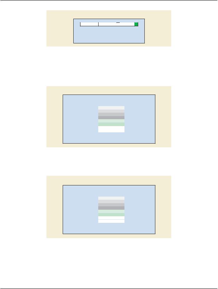
Bits Allocated = 16
Bits Stored = 12
High Bit = 11
Figure D.2-1. Example 1 of Pixel and Overlay Data Cells
Figure D.2-2 Example 2 of Pixel and Overlay Data Cells has been retired. See PS3.3 2014c.
Example 3: Pixel and Overlay Data Cells
|
|
|
Pixel Sample 2 |
|
|
|
|
|
Pixel Sample 1 |
|
|
||||||||||
|
|
|
|
|
|
|
|
|
|
|
|
|
|
|
|
|
|
|
|
|
|
15 |
14 |
13 |
12 |
11 |
10 |
9 |
|
8 |
7 |
6 |
5 |
4 |
3 |
2 |
1 |
|
0 |
||||
|
|
|
|
|
|
|
|
|
|
|
|
|
|
|
|
|
|
|
|
|
|
|
|
|
Pixel Sample 4 |
|
|
|
|
|
Pixel Sample 3 |
|
|
||||||||||
|
|
|
|
|
|
|
|
|
|
|
|
|
|
|
|
|
|
|
|
|
|
15 |
14 |
13 |
12 |
11 |
10 |
9 |
|
8 |
7 |
6 |
5 |
4 |
3 |
2 |
1 |
|
0 |
||||
|
|
|
|
|
|
|
|
|
|
|
|
|
|
|
|
|
|
|
|
|
|
Bits Allocated = 8
Bits Stored = 6
High Bit = 5
Figure D.2-3. Example 3 of Pixel and Overlay Data Cells
Example 4: Overlay Data Cells
15  14
14 13
13 12
12 11 10
11 10 9
9  8
8  7
7  6
6  5
5  4
4  3
3  2
2  1 0
1 0
Bits Allocated = 1
Bits Position = 0
Figure D.2-4. Example 4 of Overlay Data Cells
Note
In this example, the Overlay Bits are numbered in the same manner that Pixel Cells are numbered in the other examples in this Annex. That is Overlay Bit 1 is the first bit of the Overlay Plane, encoded from left to right and top to bottom, a row at a time.
- Standard -
Page 122 |
DICOM PS3.5 2020a - Data Structures and Encoding |
Example 5: Single Bit (Binary) Pixel Data Cells
15  14
14 13
13 12
12 11 10
11 10 9
9  8
8  7
7  6
6  5
5  4
4  3
3  2
2  1 0
1 0
Bits Allocated = 1
Bits Stored = 1
High Bit = 0
Figure D.2-5. Example 5 of Single Bit Pixel Data Cells (VR=OW)
D.3 Examples of Float and Double Float Pixel Data
Float Pixel Data having the Value Representation OF always has 32 bits allocated; the resulting byte streams pictured in Figure D.3- 1 are as they would be transmitted across a network and/or stored on media.
Float Pixel Data Byte Stream (VR = OF); 32 bits allocated)
Little Endian Transfer Syntax
|
7 |
6 |
5 |
4 |
3 |
2 |
1 |
0 |
|
byte 0 |
|
MSb |
Pixel 1.1 |
LSb |
|||||
byte 1 |
|
MSb |
Pixel 1.2 |
LSb |
|||||
byte 2 |
|
MSb |
Pixel 1.3 |
LSb |
|||||
byte 3 |
|
MSb |
Pixel 1.4 |
LSb |
|||||
byte 4 |
|
MSb |
Pixel 2.1 |
LSb |
|||||
byte 5 |
|
MSb |
Pixel 2.2 |
LSb |
|||||
|
|
|
|
|
... |
|
|
|
|
|
|
|
|
|
... |
|
|
|
|
|
MSb = Most Significant Bit |
|
|||||||
|
LSb = Least Significant Bit |
|
|||||||
Figure D.3-1. Sample Float Pixel Data Byte Streams for VR = OF
Double Float Pixel Data having the Value Representation OD always has 64 bits allocated; the resulting byte streams pictured in Figure D.3-2 are as they would be transmitted across a network and/or stored on media.
Double Pixel Data Byte Stream (VR = OD; 64 bits allocated)
Little Endian Transfer Syntax
|
7 |
6 |
5 |
4 |
3 |
2 |
1 |
0 |
|
byte 0 |
|
MSb |
Pixel 1.1 |
LSb |
|||||
byte 1 |
|
MSb |
Pixel 1.2 |
LSb |
|||||
byte 2 |
|
MSb |
Pixel 1.3 |
LSb |
|||||
byte 3 |
|
MSb |
Pixel 1.4 |
LSb |
|||||
byte 4 |
|
MSb |
Pixel 2.1 |
LSb |
|||||
byte 5 |
|
MSb |
Pixel 2.2 |
LSb |
|||||
|
|
|
|
|
... |
|
|
|
|
|
|
|
|
|
... |
|
|
|
|
|
MSb = Most Significant Bit |
|
|||||||
|
LSb = Least Significant Bit |
|
|||||||
Figure D.3-2. Sample Float Pixel Data Byte Streams for VR = OD
- Standard -

DICOM PS3.5 2020a - Data Structures and Encoding |
Page 123 |
E DICOM Default Character Repertoire (Normative)
The default repertoire for character strings in DICOM is the Basic G0 Set of the International Reference Version of ISO 646:1990 (ISO IR-6). In addition, the Control Characters LF, FF, CR, TAB and ESC are supported. These control characters are a subset of the C0 set defined in ISO 646:1990 and ISO 6429:1990.
The byte encoding of the Default Character Repertoire is pictured in Table E-1. This table can be used to derive both ISO column/row byte values and hex values for encoded representations (see Section 6.1.1).
Table E-1. DICOM Default Character Repertoire Encoding
|
|
|
|
b8 |
0 |
0 |
0 |
0 |
0 |
0 |
0 |
0 |
|
|
|
|
b7 |
0 |
0 |
0 |
0 |
1 |
1 |
1 |
1 |
|
|
|
|
b6 |
0 |
0 |
1 |
1 |
0 |
0 |
1 |
1 |
|
|
|
|
b5 |
0 |
1 |
0 |
1 |
0 |
1 |
0 |
1 |
b4 |
b3 |
b2 |
b1 |
|
00 |
01 |
02 |
03 |
04 |
05 |
06 |
07 |
0 |
0 |
0 |
0 |
00 |
|
|
SP |
0 |
@ |
P |
` |
p |
0 |
0 |
0 |
1 |
01 |
|
|
! |
1 |
A |
Q |
a |
q |
0 |
0 |
1 |
0 |
02 |
|
|
" |
2 |
B |
R |
b |
r |
0 |
0 |
1 |
1 |
03 |
|
|
# |
3 |
C |
S |
c |
s |
0 |
1 |
0 |
0 |
04 |
|
|
$ |
4 |
D |
T |
d |
t |
0 |
1 |
0 |
1 |
05 |
|
|
% |
5 |
E |
U |
e |
u |
0 |
1 |
1 |
0 |
06 |
|
|
& |
6 |
F |
V |
f |
v |
0 |
1 |
1 |
1 |
07 |
|
|
' |
7 |
G |
W |
g |
w |
1 |
0 |
0 |
0 |
08 |
|
|
( |
8 |
H |
X |
h |
x |
1 |
0 |
0 |
1 |
09 |
TAB |
|
) |
9 |
I |
Y |
i |
y |
1 |
0 |
1 |
0 |
10 |
LF |
|
* |
: |
J |
Z |
j |
z |
1 |
0 |
1 |
1 |
11 |
|
ESC |
+ |
; |
K |
[ |
k |
{ |
1 |
1 |
0 |
0 |
12 |
FF |
|
, |
< |
L |
\ |
l |
| |
1 |
1 |
0 |
1 |
13 |
CR |
|
- |
= |
M |
] |
m |
} |
1 |
1 |
1 |
0 |
14 |
|
|
. |
> |
N |
^ |
n |
~ |
1 |
1 |
1 |
1 |
15 |
|
|
/ |
? |
O |
_ |
o |
|
- Standard -

Page 124 |
DICOM PS3.5 2020a - Data Structures and Encoding |
- Standard -

DICOM PS3.5 2020a - Data Structures and Encoding |
Page 125 |
F Encapsulated Images As Part of A DICOM
Message (Informative)
The following remarks apply generally to communicating an encoded image within a message structure according to the DICOM Standard:
a)In the course of including an encoded image in a DICOM message, the encoding is not changed. The encoded data stream is merely segmented and encapsulated according to the protocols of the DICOM Standard. After unpacking the DICOM message, the encoded data stream can be fully reconstructed at the receiving node.
b)TheobjectdefinitionoftheDICOMStandardisalwaysdeterminingformatandotherchoicesthataspecificencodingimplementation may offer. The encoded image must be consistent with the definition of the object of which the encoded image is part. For example:
1)If the object is defined to contain 10-bit pixel data, it is assumed that the encoding process is one that accepts at least 10-bit data. Hence, there is no need for defining separate Transfer Syntaxes, e.g., for 8-bit or 12-bit implementations. Any 12-bit implementation is assumed to operate in an 8-bit process if the object is defined to contain 8-bit data.
2)If the image of an object is interleaved, the encoding process must reproduce the interleaving.
c)Specifications in the encoding file header must be consistent with the DICOM Message header, e.g., regarding the number of rows and columns.
d)The byte order specification of an encoded file is not altered in the course of encapsulating it in a DICOM message.
F.1 Encapsulated JPEG Encoded Images
The International Standards Organization (ISO/IEC JTC1/SC2/WG10) has prepared an International Standard, ISO 10918-1 (JPEG Part 1) and International Draft Standard ISO 10918-2 (JPEG Part 2), for the digital compression and coding of continuous-tone still images. This standard is collectively known as the JPEG Standard.
Part 1 of the JPEG Standard sets out requirements and implementation guidelines for the coded representation of compressed image data to be interchanged between applications. The processes and representations are intended to be generic in order to support the broadrangeofapplicationsforcolorandgrayscalestillimagesforthepurposeofcommunicationsandstoragewithincomputersystems. Part 2 of the JPEG Standard defines tests for determining whether implementations comply with the requirements of the various en- coding and decoding processes specified in Part 1 of the JPEG Standard.
The JPEG Standard specifies lossy and lossless code processes. The lossy coding is based on the discrete cosine transform (DCT), permitting data compression with an adjustable compression ratio. The lossless coding employs differential pulse code modulation (DPCM).
The JPEG Standard permits a variety of coding processes for the coder and decoder. These processes differ in coding schemes for the quantified data and in sample precision. The coding processes are consecutively numbered as defined in the International Draft Standard ISO 10918-2 (JPEG Part 2), and are summarized in Table F.1-1. The simplest DCT-based coding process is referred to as Baseline Sequential with Huffman Coding for 8-bit Samples.
- Standard -