Материал: m013800e

Connect the D-SUB connection plug as follows:
9 pol. D-SUB |
Signal |
Direction |
Description |
1 |
- |
|
not used |
2 |
RxD |
In |
Signal received (4 wire) |
3 |
TxD (RxD) |
Out |
Signal transmitted (received) (2 wire) |
4 |
DE |
Out |
Repeater control signal |
5 |
GND |
PWR |
Signal and supply earth (ground) |
6 |
Vcc |
PWR |
Supply voltage, +5V (only for external connections) |
7 |
RxD inverted |
In |
Receive signal with inverted level (4 wire) |
8 |
TxD (RxD) inverted |
Out |
Send signal with inverted level (receive) (2 wire) |
9 |
- |
|
not used |
Table 2.2: Pin assignment for 4 wire connections
The connection point is mechanically lowered so that fitting into a 80 mm deep switch cabinet is possible following the plug-in connection.
The pin assignment is 2 wire operation conforms with the Profibus assignment. Thus the Profibus wiring components can be used.
One application possibility is the connection of a Yokogawa Interface. This PCB supports the MODBUS protocol. The standard setting is the RTU mode (see chapter MODBUS) and 4 wire connections. The pin assignment is as follows:
9 pol. D-SUB |
Signal |
25 pol. SUB D |
Signal |
Colour |
1 |
- |
- |
- |
- |
2 |
RxD |
14 |
SD A |
brown |
3 |
TxD (RxD) |
16 |
RD A |
red |
4 |
DE |
- |
- |
- |
5 |
GND |
25 |
SG |
yellow/black |
6 |
Vcc |
- |
- |
- |
7 |
RxD (inv) |
18 |
SD B |
black (brown pair) |
8 |
TxD(RxD) (inv) |
19 |
RD B |
black (red pair) |
9 |
- |
- |
- |
- |
Table 2.3: Yokogawa interface pin assignment
Switches for RS 485
The setting for 2 or 4 wire connections and switching in or out of the corresponding matching resistors is made by switches, covered by the enclosure. To access the switches remove the enclosure from the coupler/controller. A protruding locking device can be found on the bottom of the unit on the two short sides. Push the two short sides apart to permit the enclosure to be pushed past the unit metal plate. Simultaneously press from above on the right hand section of the coupler/controller, which is the supply side.
16 |
MODBUS / Coupler/controller |
15.12.99
The enclosure prevents unintentional changes of the settings during later operation. If, however, access to the settings is required in the case of a fault, ensure that the previous settings are marked on a label.
After changing the settings push the enclosure back onto the coupler/controller. Note that it may be necessary to lightly push the wide side of the coupler/controllers to the side when the metal plate does not easily slide into the enclosure. In addition it may be necessary to push the rotary switches into the cut-outs provided.
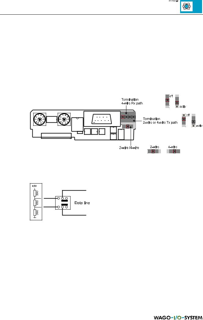
The switch on the interface printed circuit board for setting 2 and 4 wire connections or for the matching resistors can be found in the following illustration:
Fig. 2.9: Interface printed circuit board
For 2 wire connections RxD and TxD are short circuited. By the termination, a series circuit comprising of 3 resistors is connected to the bus conductor terminations.
Fig. 2.10: Internal matching resistors and interface switches
The standard setting for the supplied coupler/controller is a 2 wire connection and a switched off matching resistor.
Four wire connections can be terminated as well as the receiver line.
MODBUS / Coupler/controller |
17 |
15.12.99

2.5.2 RS 232
Coupler : 750-314 and 750-316
Controller: 750-814 and 750-816
The MODBUS can also be operated directly on an RS 232 interface. The D-SUB connection plug is connected in this case as follows:
9-pol. D-SUB |
Signal |
Direction |
Description |
1 |
- |
|
not used |
2 |
TxD |
Out |
Signal received |
3 |
RxD |
In |
Signal transmitted |
4 |
- |
|
not used |
5 |
GND |
PWR |
Signal and supply earth (ground) |
6 |
- |
|
not used |
7 |
- |
|
not used |
8 |
- |
|
not used |
9 |
- |
|
not used |
Table 2.4: RS 232 plug assignment
The pin assignment permits the use of commercially available 9 pole 1:1 sockets/ plug lines for direct connection to a PC.
18 |
MODBUS / Coupler/controller |
15.12.99
3 Technical Data
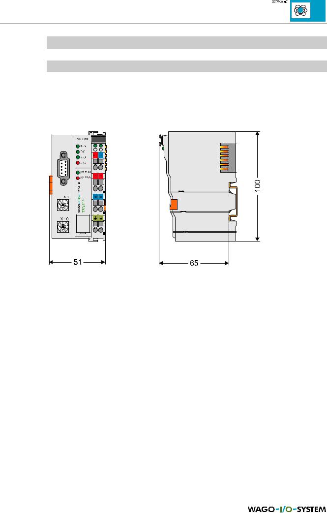
3.1 Dimensions
Fig. 3.1: Dimensions of coupler/controller
MODBUS / Technical data |
19 |
15.12.99

3.2 Coupler
SYSTEM DATA:
|
750-312 |
750-315 |
750-314 |
|
750-316 |
|
|
|
|
|
|
Max. number of nodes |
99 with repeater |
|
1 |
||
Max. number of I/O points |
about 6,000 (depends on master) |
256 |
|||
Transmission medium |
|
Shielded Cu cable 2 (4) x 0.25 mm² |
|
|
|
Max. length of bus line |
1,200 m (depends on baud rate/on the |
about 5 m |
|||
Baud rate |
150-19,200 bauds |
1.2-115.2 kbauds |
150-19,200 bauds |
|
1.2-115.2 kbauds |
Type of transmission |
RS 485 |
RS 232 |
|||
Table 3.1: System data, coupler |
|
|
|
|
|
TECHNICAL DATA:
|
750-312, 750-314, 750-315, 750-316 |
|
|
Max. number of I/O modules |
64 |
Digital points per node |
256 (inputs and outputs) |
Analogue points per node |
128 (inputs and outputs) |
Configuration possibility |
DIP switch and decimal coder |
|
via PC or PLC device |
Bus coupler connection |
1 x D-Sub 9 |
Voltage supply |
24 V DC (-15%/+20%) |
Internal current consumption |
350 mA |
Current supply |
85 mA typ. |
|
580 mA max. |
Power jumper contacts |
Blade / spring contact, |
|
slide contacts, self-cleaning |
Voltage power jumper contacts |
24 V DC |
Current power jumper contacts |
10 A DC |
Max. current supply at intern. |
1,65 A |
Data contacts |
Slide contacts, 2,5ÿ hart gold-plated |
|
self-cleaning |
Housing material |
Polycarbonate, polyamide 6.6 |
Marking |
Standard marker cards WAGO BR247/278 |
|
Marking cards 8 x 47 mm |
Wire connection |
CAGE CLAMP, 0.08 mm² - 2.5 mm² |
Vibrations-/Schockfestigkeit |
IEC 68-2-6 / IEC 68-2-27 |
Fitting position |
any |
System of protection |
IP 20 |
Insulation |
500 V system/supply |
Operating temperature |
0 °C ... +55 °C |
Dimensions in mm |
51 x 65* x 100 (*from upper edge of DIN 35 rail) |
Table 3.2: Technical data, coupler |
|
20 |
MODBUS / Technische Daten |
15.12.99