Материал: m013800e
Digital Outputs (Standard with diagnostics)
PN 750-506
Technical description:
The power supply is provided by a series-connected supply module for the respective operating voltage. Power connections are made automatically from module to module via the internal P.J.C.s when snapped onto the DIN rail.
Attention:
The lowest power jumper contact is not carried out for some modules (e.g. 4-channel)! A module which needs all contacts (e.g. 2 channel digital) may not be connected to the right hand side of modules which do not have 3 power jumper contacts (e.g. 4 channel modules).
Using the digital outputs with diagnostic bit outputs (750-506) allows verification of the I/O channel by the connected bus. Example: a short-circuit at the output or an open circuit will set the appropriate error bit true indicating I/O failure. In this configuration the function module includes 2 digital outputs and 2 separate digital inputs. For the digital outputs with diagnostic four-conductor devices (V+; 0V; signal; ground) are standard. All digital outputs are short-circuit protected.
In case of overloads a supply module with fuse (750-601) must be connected on the line side to protect the output modules.
The standard numerical assignment for bus operations is from left to right, starting with the LSB. The positions of the different I/O modules in the configured node/station are selectable by the user. A block type configuration is not necessary. When using I/O modules with diagnostics, the existing inputs must be considered accordingly in the configuration of the Node/station. The Output module can be connected to all buscouplers of the WAGOÇI/OÇSYSTEM.
Digital Outputs 750-506 |
1 |
:$*2Ç, 2Ç6<67(0
Technical Data:
Item Number 750-
Number of outputs
Current consumption (internal) Nominal voltage
Kind of load
Output current (DC)
Diagnostics
Current consumption (internal) Isolation
Internal bit width
Configuration
Operating temperature
Wire connection
Dimensions (mm)WxHxL
506
2
15 mA
24V DC (-15%/+20%)
resistive, inductive, lamps
0.5 A
open circuit, overload
15 mA typ. + load
500 V system / power supply
4 in, 4 out
without address or configuration adjustment
0°C....+55°C
CAGE CLAMP; 0.08 to 2.5mm2
12 x 64* x 100 (*from upper edge of carrier rail)
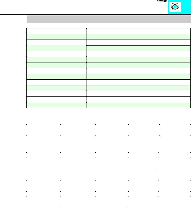
The output bits control the state of the outputs.
|
|
|
Bit 3 |
Bit 2 |
Bit 1 |
Bit 0 |
|
function |
|
no function |
no function |
controls O2 |
controls O1 |
The input bits show the state of the outputs.
|
Bit 3 |
Bit 2 |
Bit 1 |
Bit 0 |
function |
diagnostics O2 |
diagnostics O2 |
diagnostics |
diagnostics O1 |
|
|
|
O1 |
|
output follows |
0 |
0 |
0 |
0 |
output bit |
|
|
|
|
no load is |
0 |
1 |
0 |
1 |
connected |
|
|
|
|
short circuit |
1 |
0 |
1 |
0 |
power supply |
1 |
1 |
1 |
1 |
too low* |
|
|
|
|
*The diagnostic bits refer to a hysteresis: If the voltage of the field side is higher than 11V in the falling circle, they are switched on. If the voltage is lower than 15,5 V in the growing circle, they are switched off.
Digital Outputs 750-506 |
2 |
:$*2Ç, 2Ç6<67(0
Digital Outputs (Solid State Relay)
PN 750-509
Technical Description
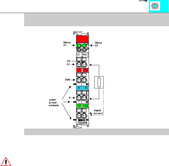
The power supply for the solid state relay module is connected by a series-connected supply module for the respective operating voltage of 230 V. Power connections are made automatically from module to module via the internal P.J.C.s when snapped onto the DIN rail.
Attention:
The lowest power jumper contact is not carried out for some modules (e.g. 4-channel)! A module which needs all contacts (e.g. 2 channel digital) may not be connected to the right hand side of modules which do not have 3 power jumper contacts (e.g. 4 channel modules).
The power supply of the control side is not made via the power jumper contacts but directly from the electronics. The respective output contacts of the switching element are therefore always positioned at the field side. One termination point of these contacts must be directly connected to the power supply. For the digital outputs four-conductor devices (V+; 0V; signal; ground) are standard. All digital outputs are short-circuit protected. In case of overloads a supply module with fuse (750-609) must be connected on the line side to protect the output modules.
The standard numerical assignment for Bus operation is from left to right, starting with the LSB. The positions of the different inputs in the configured station are via the user’s choice. A block type assembly is not necessary. The Output module can be connected to all buscouplers of the WAGOÇI/OÇSYSTEM.
Digital Outputs 750-509 |
1 |
:$*2Ç, 2Ç6<67(0
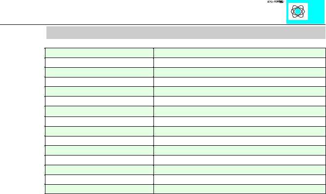
Technical Data:
Item Number 750-
Number of outputs
Current consumption (internal)
Switching voltage
Switched current
Speed of operation
Volume resistance
Impulse current
Overvoltage protection
Isolation
Internal bit width
Configuration
Operating temperature
Wire connection
Dimensions (mm)WxHxL
509
2
10 mA
0 V...230 V AC/DC
300 mA AC max.
1.65 ms typ., 5 ms max.
2.1Ω typ., 3.2 Ω max.
0.5A (20 s), 1.5 A (0.1 s) >+/- 380 V (suppressor diode)
1.5kV system / power supply
2
without address or configuration adjustment
0°C....+55°C
CAGE CLAMP; 0.08 to 2.5mm2
12 x 64* x 100 (*from upper edge of the carrier rail)
Digital Outputs 750-509 |
2 |
:$*2Ç, 2Ç6<67(0
Pulsewidth Module
PN 750-511
Technical Description:
This description is for hard and software version X X X X 2 B 0 2- - - - . The part number is displayed on the right side of the module.
The initial pre-programmed base frequency is for 250 Hz. The resolution is 10 Bits and the pulsewidth is modulated.
Attention:
The lowest power jumper contact is not carried out for some modules (e.g. 4-channel)! A module which needs all contacts (e.g. 2 channel digital) may not be connected to the right hand side of modules which do not have 3 power jumper contacts (e.g. 4 channel modules).
The following description is preliminary and is applicable to the factory configuration.
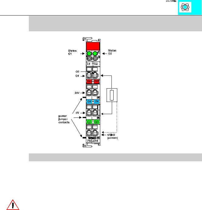
The pulsewidth output module 750-511 produces a binary modulated signal of 24 V. The connection of the consuming device should be made via the „O“ and 0 V (common) contacts of the module. The distribution of the 24 V DC is made via the power jumper contacts. If galvanic isolation is desired, a new power feed via a 750-602 is required.
The PWM module can be connected to all buscouplers of the WAGOÇI/OÇSYSTEM (except for the economy type).
Pulsewidth Module 750-511 |
1 |
:$*2Ç, 2Ç6<67(0