Материал: m013800e
Counter modules
PN 750-404, 750-404/000-001, 750-404/000-002 750-404/000-003, 750-404/000-004
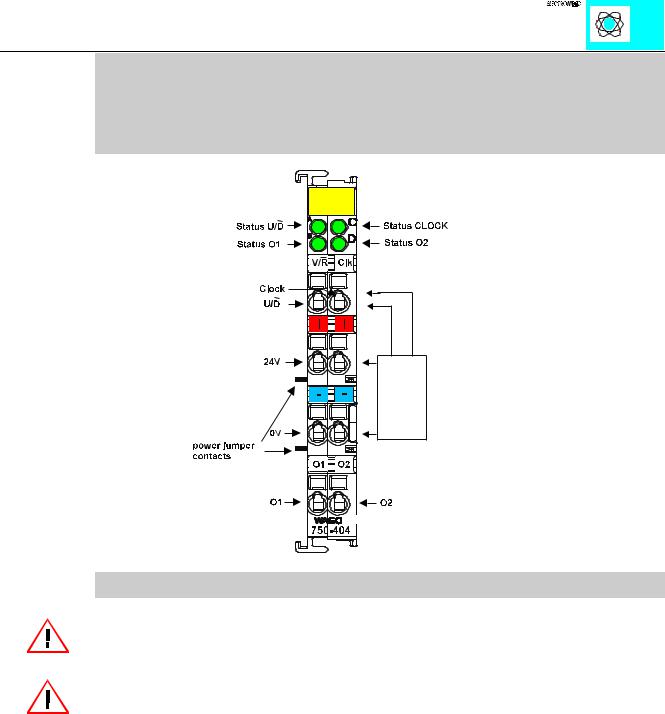
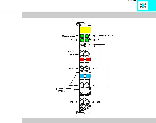
Up/Down Counter 100 kHz, 750-404
Technical Description:
Attention! The description that is in the I/O ring binder data pages (88-530/013-600 dated 7/96) is not correct. The bottom contacts are additional outputs.
Attention:
The lowest power jumper contact is not carried out for some modules (e.g. 4-channel)! A module which needs all contacts (e.g. 2 channel digital) may not be connected to the right hand side of modules which do not have 3 power jumper contacts (e.g. 4 channel modules).
The described configuration is counter with up/down input.
The following description is preliminary and is applicable to the factory configuration.
The counter module is able to run with all WAGOÇI/OÇSYSTEM bus-couplers (except for the economy type).
Counter Module 750-404 |
1 |
|
:$*2 , 2 6<67(0 |
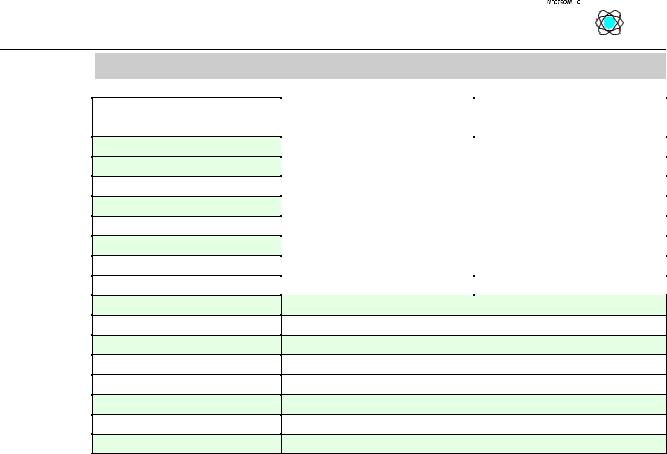
Technical Data:
Item Number: 750-
Number of outputs
Output current
Number of counter
Input current (internal)
Nominal voltage
Signal voltage (0)
Signal voltage (1)
Switching rate
Output current
Counter size
Isolation
Bit width
Configuration
Operating temperature
Wire connection
Size (mm)WxHxD
|
|
|
|
|
|
|
|
|
|
|
|
|
|
|
|
|
|
|
|
|
|
|
|
|
|
|
|
|
|
|
|
404, 404/000-001 |
|
404/000-002 |
|
|
|||
404/000-004 |
|
|
|
|
|
|
|
2 |
|
|
|
|
|
|
|
0.5 A |
|
|
|
|
|
|
|
1 |
|
|
|
|
|
|
|
70 mA |
|
|
|
|
|
|
|
24 V DC (-15% +20%) |
|
||||||
-3V.....+5V DC |
|
|
|
|
|
|
|
+15V...+30V DC |
|
||||||
100 kHz |
|
10 kHz max. |
|
||||
5 mA typ.
32 Bit
500 V system/power supply
32 Bit (8 Bit verification; 8 bit not used)
none, optional with software parameter
0°C....+55°C
CAGE CLAMP; 0.08 to 2.5mm2
12 x 64* x 100 (*from upper edge of the carrier rail)
Counter Module 750-404 |
2 |
|
:$*2 , 2 6<67(0 |
Organization of the inand output data:
The counter begins processing with pulses at the CLOCK input. The changes from 0 V to 24 V are counted.
The counter counts up, if the input U/D is set at 24 V. With an open circuit input or 0 V the counter counts backwards.
The two bottom contacts each include another output. These outputs are activated through bits in the control byte.
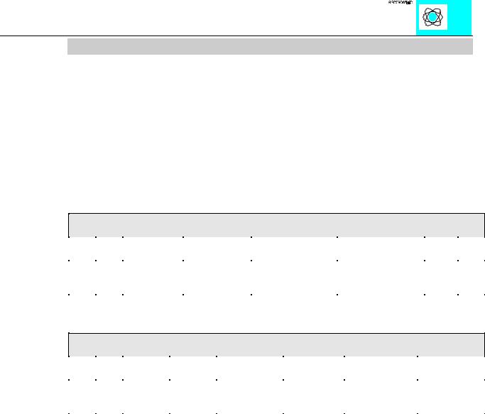
The control byte has the following bits:
Control Byte
Bit 7 |
Bit 6 |
Bit 5 |
Bit 4 |
Bit 3 |
Bit 2 |
Bit 1 |
Bit 0 |
|
|
|
|
|
|
|
|
0 |
x |
Set Counter |
Block Counter |
Output value at |
Output value at |
x |
x |
|
|
|
|
output O2 |
output O1 |
|
|
|
|
|
|
|
|
|
|
The status byte has the following bits:
Status Byte
Bit 7 |
Bit 6 |
Bit 5 |
Bit 4 |
Bit 3 |
Bit 2 |
Bit 1 |
Bit 0 |
|
|
|
|
|
|
|
|
x |
x |
Counter is |
Counter is |
actual signal at |
actual signal |
actual signal at |
actual signal at |
|
|
set |
blocked |
O2 |
at O1 |
input U/D |
input CLOCK |
|
|
|
|
|
|
|
|
With the control and status-byte the following tasks are possible:
Set the counter: Put Bit 5 into the control byte. The counter with the 32 bit value is loaded into output bytes 0-3. As long as the bits are set, the counter can stop and information is stored. The ensuing data of the counter will be conveyed to the status byte.
Blocking the counter: Bit 4 is set into the control byte, then the count process is suppressed. Bit 4 in the status byte communicates the suppression of the counter.
Set the outputs: Bits 2 and 3 set the additional two outputs of the counter module.
The result of the counter is in binary.
Counter Module 750-404 |
3 |
|
:$*2 , 2 6<67(0 |
An example:
The counter is set with “Set Counter” to the value 0x0000.0000
- 0X1X.XXXX, 0x00, 0x00, 0x00, 0x00 are carried over as output value (carry over the control-byte and the new counter position),
-wait until the input value is 0X1X.XXXX, 0x00, 0x00, 0x00, 0x00 (the status-byte shows the loading feedback) ,
-carry over 0x00, 0x00, 0x00, 0x00, 0x00 as output value (release counter).
Wait for the first and further counting pulse |
|
-the input value is XX00.XXXX, 0x00, 0x00, 0x00, 0x00 |
(no counting pulse received) |
-the input value is XX00.XXXX, 0x00, 0x00, 0x00, 0x01 |
(1 counting pulse received) |
-the input value is XX00.XXXX, 0x00, 0x00, 0x00, 0x02 |
(2 counting pulses received) |
-.................
-the input value is XX00.XXXX, 0xFF, 0xFF, 0xFF, 0xFF (maximum counting position is reached)
-the input value is XX00.XXXX, 0x00, 0x00, 0x00, 0x00 (a further counting pulse causes an overflow)
-the input value is XX00.XXXX, 0x00, 0x00, 0x00 0x01, (a further counting pulse is received)
Notes: 0x23 is a value in hexadecimal form 0101.1001 is a value in binary form
“X” is used if the value at this position is without any significance.
Counter Module 750-404 |
4 |
|
:$*2 , 2 6<67(0 |
Counter with enable input 750-404/000-001
Technical description:
The counter module also can be ordered as counter with enable input (750-404/000- 001).
The counter begins processing with pulses at the CLOCK input. The changes from 0 V to 24 V are counted.
The counter counts down if the input U/D is set at 24 V. With an open circuit input or 0 V the counter counts up.
The data format of the module is 4 bytes data and a control/status byte. The module is a 32 Bit counter. The ID Code os 180 (0xB4). The format of input and output data is the same as 750-404.
The counter module is able to run with all WAGOÇI/OÇSYSTEM bus-couplers (except for the economy type).
Counter Module 750-404 |
5 |
|
:$*2 , 2 6<67(0 |