Материал: m013800e
7.4 Class and degree of protection
Class of protection
Class of protection acc. to IEC 536 (VDE 0106, part 1):
The ground (earth) connection to the DIN carrier is necessary !
Degree of protection |
|
Degree of protection |
|
acc. to IEC 529: |
IP 20 |
|
(protection against direct contact with standard probes) |
Protec. against foreign bodies: |
Diameter > 12 mm |
Protection against water: |
No particular protection |
We offer enclosures made of aluminium die-cast, polyester or stainless steel with the IP 65 degree of protection to protect against water infiltration (see
WAGO-I/O-SYSTEM catalogue).
7.5 Specifications and test results
Approvals: |
UI listed |
E175199 |
|
|
E198726 |
|
CSA |
LR 18677-57 |
|
|
(750-xxx/ 1xx-xxx) |
Ex approvals: |
Atex |
prEN50021 |
|
|
EEX nV II T4 |
|
Ul listed |
Class I Div2 ABCD T4A |
Conformity marking: |
CE |
|
MODBUS / General conditions |
81 |
15.12.99

7.6 Electromagnetic compatibility
The following requirements for electromagnetic compatibility are fulfilled by all modules of the WAGO-I/O-SYSTEMÿ(except for 750-630 and 750-631).
Immunity to interference EN 50082-2 (95)
EN 61000-4-2 |
4 kV/8 kV |
(2/4) |
B |
|
|
|
|
EN 61000-4-3 |
10 V/m 80 % AM |
(3) |
A |
|
|
|
|
EN 61000-4-4 |
2 kV |
(3/4) |
B |
|
|
|
|
EN 61000-4-6 |
10 V/m 80 % AM |
(3) |
A |
|
|
|
|
Immunity to interference EN 50081-2 (94) |
|
|
|
|
|
|
|
EN 55011 |
30 dBµV/m |
(30 m) |
A |
|
|
|
|
|
37 dBµV/m |
|
|
|
|
|
|
Table 7.4: Electromagnetic compatibility |
|
|
|
82 |
MODBUS / General conditions |
15.12.99
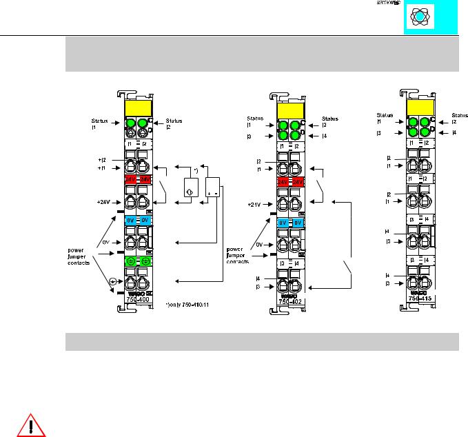
Digital Inputs (24 V AC/DC, 120 V AC, 230 V AC, 48 V DC) PN: 750-400...415
Technical description
The supply is applied by a series-connected termination to each I/O module for the respective operating voltage. Power connections are made automatically from module to module when snapped onto the DIN rail.
Attention:
The lowest power jumper contact is not carried out for some modules (e.g. 4-channel)! A module which needs all contacts (e.g. 2 channel digital) may not be connected to the right hand side of modules which do not have 3 power jumper contacts (e.g. 4 channel modules).
All 2-channel digital inputs are 4-conductor devices allowing the direct connection of 4- conductor sensors with the terminations V+, 0V, ground and signal.
The 4-channel digital inputs are suitable for the direct connection of two 3-conductor sensors (V+, 0V, signal). The power distribution module 750-614 is available for the connection of more sensors to V+ and 0V.
The modules 750-408 and 750-409 are low-side switching.
A 2-wire proximity switch can be connected to the modules 750-410 and 750-411. RC filters are series-connected to the 5, 24 and 48 V versions for noise rejection and switch debouncing. They are available with time constants of 3.0 ms and 0.2 ms.
The standard numerical assignment for bus operations is from left to right, starting with the LSB. The positions of the different I/O modules in the configured node/station are selectable by the user. A block type configuration is not necessary.
The Input module can be connected to all buscouplers of the WAGOÇI/OÇSYSTEM.
Digital Inputs 750-400...415 |
1 |
:$*2Ç, 2Ç6<67(0
Technical Data:
Item Number 750-
Number of inputs
Input filter
Nominal voltage
Signal voltage (0)
Signal voltage (1)
Input current (internal)
Input current (field side)
Isolation
Internal bit width
Configuration
Operating temperature
Wire connection
Dimensions (mm) WxHxL
Item Number 750-
Number of inputs
Input filter
Nominal voltage
Signal voltage (0)
Signal voltage (1)
Input current (internal)
Input current (field side)
Isolation
Internal bit width
Configuration
Operating temperature
Wire connection
Dimensions (mm)WxHxL
400 |
|
401 |
|
402 |
|
403 |
|
2 |
|
|
4 |
||
3 ms |
|
0.2 ms |
|
3 ms |
|
0.2 ms |
|
|
24V DC (-15%/+20%) |
|
|
||
-3V...+5V DC (std. EN 61131 Typ 1) |
||||||
15V...30V DC (std. EN 61131 Typ 1) |
||||||
2.5 mA max. |
|
5 mA max. |
||||
|
|
5 mA typ. |
|
|
|
|
|
500 V system/power supply |
|
|
|||
|
2 |
|
|
|
4 |
|
no address or configutation adjustment
0°C....+55°C
CAGE CLAMP; 0.08 to 2.5mm2
12 x 64* x 100 (*from upper edge of carrier rail)
|
405 |
406 |
|
410* |
|
|
411* |
|
|
|
2 |
|
|
|
|
2 |
|
||
|
10 ms |
|
3 ms |
|
|
0.2 ms |
|
||
|
|
|
|
|
|
|
|
|
|
|
230 V AC |
|
120 V AC |
|
24V DC (-15%/+20%)) |
|
|||
|
(-15%/+10%) |
|
(- |
|
|
|
|
|
|
|
|
|
15%/+10%) |
|
|
|
|
|
|
|
0 V...40 V |
|
0 V..20 V |
|
-3 V ... +5 V DC (std. |
|
|||
|
AC |
|
AC |
|
EN 61131 Type 2) |
|
|||
|
79 V...1.1 UN |
|
79 V...1.1 |
|
11 V ... 30 V DC (std. |
|
|||
|
AC |
|
UN AC |
|
EN 61131 Type 2) |
|
|||
|
2 mA |
|
2.5 mA max. |
|
|||||
|
6.5 mA typ. |
|
4.5 mA typ. |
|
8 mA typ. |
|
|||
|
4 kV system/power supply |
|
500 V system/power |
|
|||||
|
|
|
|
|
|
supply |
|
||
|
|
2 |
|
|
|
|
|
|
|
|
no address or configuration adjustment |
|
|||||||
|
|
|
0°C....+55°C |
|
|
|
|
||
CAGE CLAMP; 0.08 to 2.5mm2
12 x 64* x 100 (*from upper edge of the carrier rail)
*) 2 - wire proximity switch, current without load max. 2 mA
Digital Inputs 750-400...415 |
2 |
:$*2Ç, 2Ç6<67(0

Item Number 750-
Number of inputs
Input filter
Nominal voltage
Signal voltage (0)
Signal voltage (1)
Input current (internal)
Input current (field side)
Isolation
Internal bit width
Configuration
Operating temperature
Wire connection
Dimensions (mm)WxHxL
408 |
|
409 |
|
4 |
|
3 ms |
|
0,2 ms |
24V DC (-15% / +20%) |
||
15 V...30 V DC |
||
-3 |
V...5 |
V DC |
10 mA max.
|
|
|
|
|
|
|
|
|
|
|
|
|
|
|
|
|
|
|
|
|
|
|
|
412 |
|
413 |
|
|
|
|
2 |
|
|
|
|
3 ms |
|
|
0,2 ms |
|
|
48 V DC (-15% / +20%)
-6 V ... +10 V DC
34 V ... 60 V DC
5 mA max.
3.5 mA typ.
500 V system/power supply
4 |
2 |
no address or configuration adjustment
0°C....+55°C
CAGE CLAMP; 0,08 to 2,5 mm2
12 x 64* x 100 (*from upper edge of the carrier rail)
Item Number 750-
Number of inputs
Input filter /
Conversion time
Nominal voltage
Signal voltage (0)
Signal voltage (1)
Input current (internal)
Input current (field side)
Isolation
Internal bit width
Configuration
Operating temperature
Wire connection
Dimensions (mm)WxHxL
414 |
415 |
4 |
4 |
0.2 ms |
20 ms |
|
|
5 V DC |
24 V AC/DC |
|
(-15%/+20%) |
0...0.8 V DC |
-3...+5 V DC |
|
0...+5 V AC |
2.4 V...5 V DC |
11 ... 30 V DC |
|
10 ... 27 V AC |
5 mA |
10 mA |
50 µA typ. |
7.5 mA DC |
|
7.6 9.5 mA AC |
500 V system/power supply |
500V system/power |
|
supply |
|
50 V channel/channel |
4 |
4 |
no address or configuration adjustment
0°C....+55°C
CAGE CLAMP; 0,08 to 2,5 mm2
12 x 64* x 100 (*from upper edge of the carrier rail)
Digital Inputs 750-400...415 |
3 |
:$*2Ç, 2Ç6<67(0