Материал: m013500e_x06
16• The WAGO-I/O-SYSTEM 750
Mechanical Setup
2.5.3.2 WAGO DIN Rail
WAGO carrier rails meet the electrical and mechanical requirements.
Item Number |
Description |
|
210-113 /-112 |
35 x 7.5; 1 mm; |
steel yellow chromated; slotted/unslotted |
|
|
|
210-114 /-197 |
35 x 15; 1.5 mm; |
steel yellow chromated; slotted/unslotted |
|
|
|
210-118 |
35 x 15; 2.3 mm; |
steel yellow chromated; unslotted |
|
|
|
210-198 |
35 x 15; 2.3 mm; |
copper; unslotted |
|
|
|
210-196 |
35 x 7.5; 1 mm; aluminum; unslotted |
|
|
|
|
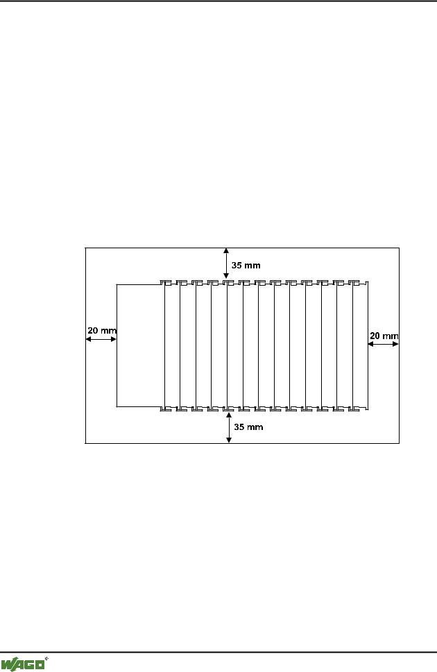
2.5.4 Spacing
The spacing between adjacent components, cable conduits, casing and frame sides must be maintained for the complete field bus node.
Fig. 2-4: Spacing |
g01xx13x |
The spacing creates room for heat transfer, installation or wiring. The spacing to cable conduits also prevents conducted electromagnetic interferences from influencing the operation.
WAGO-I/O-SYSTEM 750
DeviceNet
The WAGO-I/O-SYSTEM 750 |
• 17 |
Mechanical Setup |
|
|
|
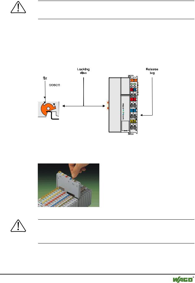
2.5.5 Plugging and Removal of the Components
Warning
Before work is done on the components, the voltage supply must be turned off.
In order to safeguard the coupler/controller from jamming, it should be fixed onto the carrier rail with the To do so, push on the upper groove of the locking disc using a screwdriver.
To pull out the fieldbus coupler/controller, release the locking disc by pressing on the bottom groove with a screwdriver and then pulling the orange colored unlocking lug.
|
|
|
|
|
|
|
|
|
|
|
|
|
|
|
|
|
|
|
|
|
|
|
|
|
|
|
|
|
|
|
|
|
|
|
|
|
|
|
|
|
|
|
|
|
|
|
|
|
|
|
|
|
|
|
|
|
|
|
|
|
|
|
|
|
|
|
|
|
|
|
|
|
|
|
|
|
|
|
|
|
|
|
|
|
|
|
|
|
|
|
|
|
|
|
|
|
|
|
|
|
|
|
|
|
|
|
|
|
|
|
|
|
|
|
|
|
|
|
|
|
|
|
|
|
|
|
|
|
|
|
|
|
|
|
|
|
|
|
|
|
|
|
Fig. 2-5: Coupler/Controller and unlocking lug |
|
|
|
|
|
g01xx12e |
||||
|
|
|
|
|
||||||
|
|
|
|
|
||||||
|
|
|
|
|
||||||
|
|
|
|
|
||||||
|
|
|
|
|
||||||
|
|
|
|
|
||||||
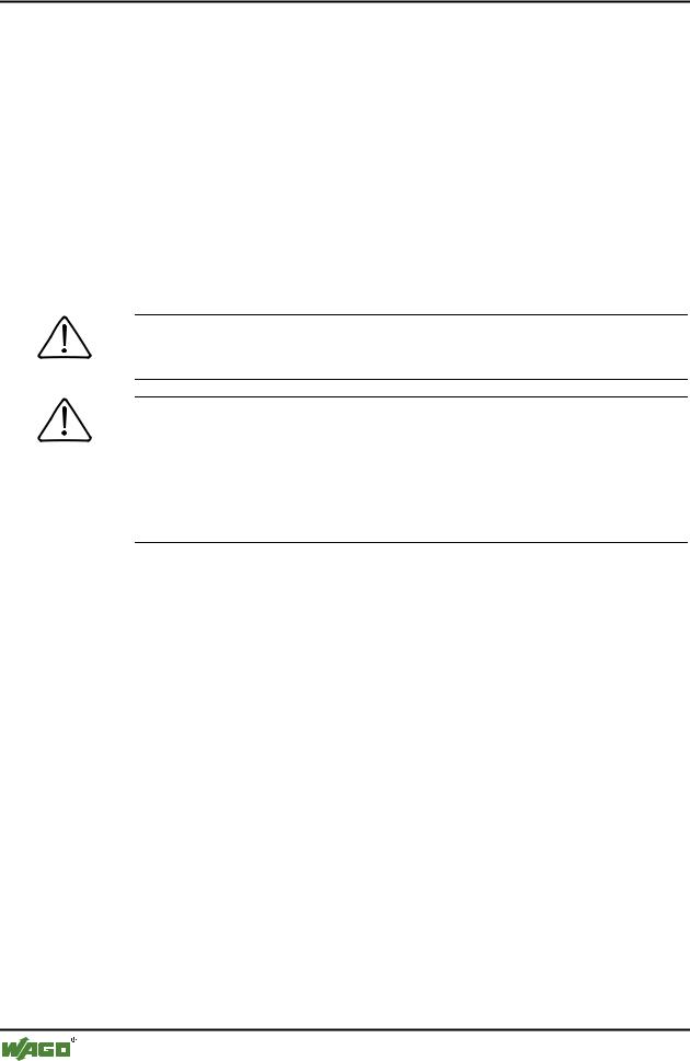
It is also possible to release an individual I/O module from the unit by pulling an unlocking lug.
Fig. 2-6: removing bus terminal |
p0xxx01x |
Danger
Ensure that an interruption of the PE will not result in a condition which could endanger a person or equipment!
For planning the ring feeding of the ground wire, please see chapter 2.6.3.
WAGO-I/O-SYSTEM 750
DeviceNet
18• The WAGO-I/O-SYSTEM 750
Mechanical Setup
2.5.6 Assembly Sequence
All system components can be snapped directly on a carrier rail in accordance with the European standard EN 50022 (DIN 35).
The reliable positioning and connection is made using a tongue and groove system. Due to the automatic locking, the individual components are securely seated on the rail after installing.
Starting with the coupler/controller, the bus modules are assembled adjacent to each other according to the project planning. Errors in the planning of the node in terms of the potential groups (connection via the power contacts) are recognized, as the bus modules with power contacts (male contacts) cannot be linked to bus modules with fewer power contacts.
Attention
Always link the bus modules with the coupler / controller, always plug from above.
Warning
Never plug bus modules from the direction of the end terminal. A ground wire power contact, which is inserted into a terminal without contacts, e.g. a 4-channel digital input module, has a decreased air and creepage distance to the neighboring contact in the example DI4.
Always terminate the fieldbus node with an end module (750-600).
WAGO-I/O-SYSTEM 750
DeviceNet
The WAGO-I/O-SYSTEM 750 |
• 19 |
Mechanical Setup |
|
|
|
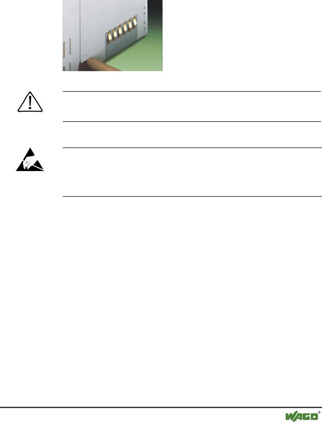
2.5.7 Internal Bus / Data Contacts
Communication between the coupler/controller and the bus modules as well as the system supply of the bus modules is carried out via the internal bus. It is comprised of 6 data contacts, which are available as self-cleaning gold spring contacts.
Fig. 2-7: Data contacts |
p0xxx07x |
Warning
Do not connect the I/O module to gold spring contacts in order to avoid soiling or scratches!
ESD (Electrostatic Discharge)
The modules are equipped with electronic components that may be destroyed by electrostatic discharge. When handling the modules, ensure that the environment (persons, workplace and packing) is well grounded. Avoid touching conductive components, e.g. gold contacts.
WAGO-I/O-SYSTEM 750
DeviceNet
20• The WAGO-I/O-SYSTEM 750
Mechanical Setup
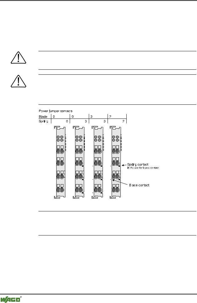
2.5.8 Power Contacts
Self-cleaning power contacts , are situated on the side of the components which further conduct the supply voltage for the field side. These contacts come as touchproof spring contacts on the right side of the coupler/controller and the bus module. As fitting counterparts the module has male contacts on the left side.
Danger
The power contacts are sharp-edged. Handle the module carefully to prevent injury.
Attention
Please take into consideration that some bus modules have no or only a few power jumper contacts. The design of some modules does not allow them to be physically assembled in rows, as the grooves for the male contacts are closed at the top.
|
|
|
|
|
|
|
|
|
|
|
|
|
|
|
|
|
|
|
|
|
|
|
|
|
|
|
|
|
|
|
|
|
|
|
|
|
|
|
|
|
|
|
|
|
|
|
|
|
|
|
|
|
|
|
|
|
|
|
|
|
|
|
|
|
|
|
|
|
|
|
|
|
|
|
|
|
|
|
|
|
|
|
|
|
|
|
|
|
|
|
|
|
|
|
|
|
|
|
|
|
|
|
|
|
|
|
|
|
|
|
|
|
|
|
|
|
|
|
|
|
|
|
|
|
|
|
|
|
|
|
|
|
|
|
|
|
|
|
|
|
|
|
|
|
|
|
|
|
|
|
|
|
|
|
|
|
|
|
|
|
|
|
|
|
|
|
|
|
|
|
|
|
|
|
|
|
|
|
|
|
|
|
|
|
|
|
|
|
|
|
|
|
|
|
|
|
|
|
|
|
|
|
|
|
|
|
|
|
|
|
|
|
|
|
|
|
|
|
|
|
|
|
|
|
|
|
|
|
|
|
|
|
|
|
|
|
|
|
|
|
|
|
|
|
|
|
|
|
|
|
|
|
|
|
|
|
|
|
|
|
|
|
|
|
|
|
|
|
|
|
|
|
|
|
|
|
|
|
|
|
|
|
|
|
|
|
|
|
|
|
|
|
|
|
|
|
|
|
|
|
|
|
|
|
|
|
|
|
|
|
|
|
|
|
|
|
|
|
|
|
|
|
|
|
|
|
|
|
|
|
|
|
|
|
|
|
|
|
|
|
|
|
|
|
|
|
|
|
|
|
|
|
|
|
|
|
|
|
|
|
|
|
|
|
|
|
|
|
|
|
|
|
|
|
|
|
|
|
|
|
|
|
|
|
|
|
|
|
|
|
|
|
|
|
|
|
|
|
|
|
|
|
|
|
|
|
|
|
|
|
|
|
|
|
|
|
|
|
|
|
|
|
|
|
|
|
|
|
|
|
|
|
|
|
|
|
|
|
|
|
|
|
|
|
|
|
|
|
|
|
|
|
|
|
|
|
|
|
|
|
|
|
|
|
|
|
|
|
|
|
|
|
|
|
|
|
|
|
|
|
|
|
|
|
|
|
|
|
|
|
|
|
|
|
|
|
|
|
|
|
|
|
|
|
|
|
|
|
|
|
|
|
|
|
|
|
|
|
|
|
|
|
|
|
|
|
|
|
|
|
|
|
|
|
|
|
|
|
|
|
|
|
|
|
|
|
|
|
|
|
|
|
|
|
|
|
|
|
|
|
|
|
|
|
|
|
|
|
|
|
|
|
|
|
|
|
|
|
|
|
|
|
|
|
|
|
|
|
|
|
|
|
|
|
|
|
|
|
|
|
|
|
|
|
|
|
|
|
|
|
|
|
|
|
|
|
|
|
|
|
|
|
|
|
|
|
|
|
|
|
|
|
|
|
|
|
|
|
|
|
|
|
|
|
|
|
|
|
|
|
|
|
|
|
|
|
|
|
|
|
|
|
|
|
|
|
|
|
|
|
|
|
|
|
|
|
|
|
|
|
|
|
|
|
|
|
|
|
|
|
|
|
|
|
|
|
|
|
|
|
|
|
|
|
|
|
|
|
|
|
|
|
|
|
|
|
|
|
|
|
|
|
|
|
|
|
|
|
|
|
|
|
|
|
|
|
|
|
|
|
|
|
|
|
|
|
|
|
|
|
|
|
|
|
|
|
|
|
|
|
|
|
|
|
|
|
|
|
|
|
|
|
|
|
|
|
|
|
|
Fig. 2-8: Example for the arrangement of power contacts |
|
g0xxx05e |
|||||||||||||||||||||||
Recommendation
With the WAGO ProServe® Software smartDESIGNER, the assembly of a fieldbus node can be configured. The configuration can be tested via the integrated plausibility check.
WAGO-I/O-SYSTEM 750
DeviceNet