Материал: Стандарт MIL-STD-202G
MIL-STD-202G
3.1Calibration.
a.Each unit of test equipment subject to calibration shall be maintained in accordance with ANSI/NCSL Z540-1.
b.System calibration shall consist of verifying the proper oscilloscope pattern while calibration unit is being energized by the shaker head at the frequency and acceleration specified in 3.2. Calibration shall also include elimination of extraneous noise which interferes with proper performance of the test.
c.Test the system with a container (size approximately ½" (12.7 mm) X 1" (25.4 mm) X 1" (25.4 mm) or smaller) which contains a 60/40 solder ball with a diameter of 0.005’’. Listen to the audible sound and observe the oscilloscope response to the solder ball.
d.Test the system with a container (size approximately 1/2" (12.7 mm) X 1" (25.4 mm) X 1" (25.4 mm) or smaller) which contains no particle, and compare the audible sound and the oscilloscope response to the results of step c to insure that particles are detectable.
3.2Test setup. The area in which the PIND system is used shall be carefully selected to avoid external interference from electrical and mechanical noise which will decrease the effectiveness of the test.
a.Set audio oscillator to 27 ±1 Hz.
b.Adjust audio amplifier to produce 3-5g (.07" (1.78 mm) - .14" (3.56 mm) displacement) at shaker head.
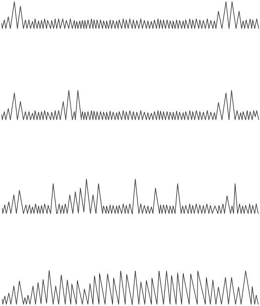
c.Check mechanical and electrical systems to minimize background noise. Background noise shall not increase more than 3 dB when shaker is placed in operation (except shaker reversal noise) and total system noise shall not exceed 20 mV. Adjust oscilloscope trace to less than 4 divisions displacement and center shaker reversal noise as shown on figure 217-2a. No other noise spikes shall be detectable.
d.Adjust audio output to comfortable level.
e.With calibration unit mounted on shaker verify proper oscilloscope and system sensitivity to produce random noise spikes of 40 mV minimum (figure 217-2c).
3.3Test procedure.
3.3.1Degausing. Devices not incorporating permanent magnets and devices being tested prior to final magnetization shall be degaused prior to PIND testing.
3.3.2Lead protection. When a device incorporates relatively long and flexible leads, the leads shall be suitably restrained from striking the shaker/fixture or striking each other during test. Care shall be taken to prevent damage caused by resonance.
3.3.3Testing. Mount unit under test in the center of acoustic transducer with largest flat surface down (paragraph 4b). Energize shaker and monitor for visual and audible evidence of loose internal material as evidenced by nonperiodic noise spikes (figure 217-2c). A single burst of noise is cause for rejection whether or not the indication can be repeated.
Allow test to proceed for approximately 5 seconds. If no failure is detected, apply a random acceleration for 3 seconds maximum or 3 to 5 shock pulses (not to exceed the rating of the device) perpendicular to the axis of vibration (see figure 217-3). Monitor for 5 seconds then repeat random vibration or shocks and monitor for an additional 5 seconds (30 seconds maximum per axis).
METHOD 217A
8 February 2002
2
MIL-STD-202G
NOTE: If excessive mechanism noise occurs (figure 217-2d) such that particle noise would be undetectable, the following action may be taken to reduce the noise:
a.Reorient unit by rotation about the shaker axis.
b.Change shaker amplitude within the specified limits.
c.Tilt shaker axis off vertical in any direction (not exceeding 30°) to provide a gravitational side component to the shaker acceleration.
d.With approval of the procuring agency, a different test frequency may be established for a given device.
e.Cancel out periodic noise.
If no particle is detected rotate unit to another flat surface providing vibration in a different axis. Repeat above test for not to exceed 30 seconds. Units shall not be tested with terminals or other non-cavity portions of the assembly in contact with the transducer.
3.3.4Marking. If specified (see 4d), those units which successfully pass PIND test shall be marked "PIND" on any surface providing existing markings are not obscured.
3.3.5Failed units. Those units which exhibit either particle noise or excessive mechanism noise which cannot be eliminated as described in 3.3.3 shall be rejected from the lot.
4.SUMMARY. The following details are to be specified in the individual specification:
a.Test frequency and acceleration if other than specified.
b.Axes of vibration if other than specified.
c.Test duration if other than specified.
d.Test acceptance marking if specified.
e.Frequency and magnitude of random noise generator shall be specified.
METHOD 217A
8 February 2002
3
MIL-STD-202G
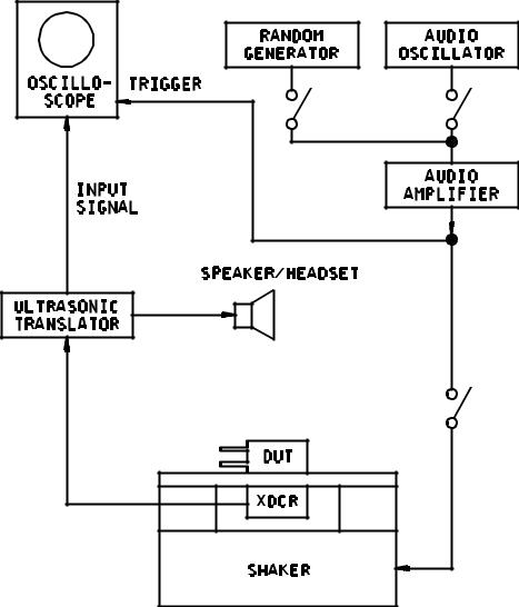
FIGURE 217-1. Typical test circuit.
METHOD 217A
8 February 2002
4
MIL-STD-202G
ACCEPTANCE CRITERIA: Each unit tested shall meet the acceptance.
SHAKER NOISE
Timebase adjusted to locate shaker reversal noise bursts at ends of oscilloscope trace. Test unit not mounted. a
INHERENT MECHANICAL NOISE
Synchronized spike may appear at different locations on time base for each unit under test. b
PARTICULATE NOISE
Non-synchronized spikes of any magnitude appear randomly and may disappear as test progresses. Unit is rejectable. c
EXCESSIVE MECHANICAL NOISE
Synchronized trace masks more than 50% of oscilloscope trace. Unit is rejectable. d
FIGURE 217-2. Representative oscilloscope traces.
METHOD 217A
8 February 2002
5
MIL-STD-202G
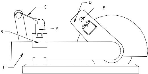
A. Unit under test.
B. Holding fixture.
C. Holding spring.
D. Angle indicator and adjustment.
E. Holding and dropping pin.
F. Dropping arm.
FIGURE 217-3. Shock test fixture.
METHOD 217A
8 February 2002
6