Материал: part03
DICOM PS3.3 2020a - Information Object Definitions |
Page 201 |
A Composite Information Object Definitions (Normative)
A.1 Elements of An Information Object Definition
Each Composite Information Object Definition is composed of the following Sections
a.IOD Description
b.IOD Entity-Relationship Model
c.IOD Module Table
d.Optionally, a Functional Group Macros Table used by the Multi-frame Functional Groups Module
Section A.1.1, Section A.1.2 and Section A.1.3 define the requirements of a) through d) above.
A.1.1 IOD Description
This Section provides a brief description of the IOD. Specifically, this description includes:
•The Real-World Object that is represented by the IOD
•Information as to the scope of the represented object if appropriate
A.1.2 IOD Entity-Relationship Model
This Section of an IOD provides the Entity-Relationship (E-R) Model that depicts the relationships of the components or Information Entities (IE) of the specified IOD. It forms an IOD specific information model. This E-R model provides the complete context of how the Composite Instance information shall be interpreted when a Composite Instance is exchanged between two DICOM Application Entities; in particular, an IOD will specify a single IE at the level below the Series IE.
EventhoughCompositeInstancesareencodedasdiscreteindividualcomponents,eachCompositeInstanceIODE-RModelrequires that all Composite Instances that are part of a specific Study shall share the same context. That is, all Composite Instances within a specific Patient Study share the same Patient and Study information; all Composite Instances within the same Series share the same Series information; etc.
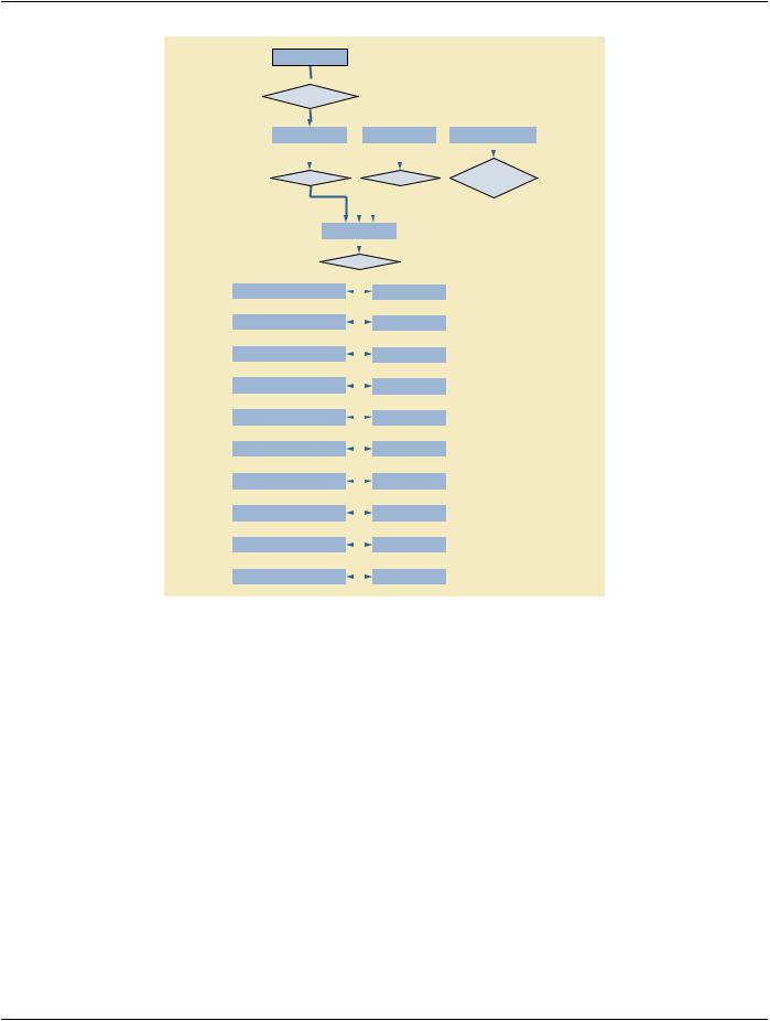
Figure A.1-1 is the DICOM Composite Instance IOD Information Model. It applies to all Patient-related Composite Instance IODs definedinAnnexA.However,asubsetofthismodelmaybespecifiedbyeachindividualCompositeInstanceIODtoaccuratelydefine the context for specific Composite Instance exchange.
The sub-sections of this Section describe the Information Entities (IE) that comprise the Composite Instance IODs defined in this Annex.
- Standard -
Page 202 |
DICOM PS3.3 2020a - Information Object Definitions |
Patient
 1 is the subject of
|
|
|
1-n |
|
|
|
|
|
|
|
|
|
|
|
|||
|
|
|
|
|
|
|
|
|
|
|
|
|
|
||||
|
Study |
|
|
|
|
|
|
|
Equipment |
|
|
Frame of Reference |
|||||
|
|
|
|
|
|
|
|
|
|
|
|
|
|
|
|
|
|
|
|
|
|
|
|
|
|
|
|
|
|
|
|
|
|
|
0-1 |
|
|
|
|
|
|
|
|
|
|
|
|
|
|
|
|
|
|
1 |
|
|
|
1 |
|
|
spatially |
||||||||||
|
|
|
|
|
|
||||||||||||
|
contains |
|
|
|
|
creates |
or temporally |
|
|||||||||
|
|
|
1-n |
|
|
|
|
|
1-n |
defines |
0-n |
||||||
|
|
|
|
|
|
|
|
||||||||||
|
|
|
|
|
|
|
|
|
|
|
|
|
|
|
|
|
|
|
|
|
|
|
|
|
|
|
|
|
|
|
|
|
|
|
|
|
|
|
|
|
|
|
|
|
|
|
|
|
|
|
|
|
|
|
|
|
|
|
|
|
|
|
|
|
|||||||
|
|
|
Series |
|
|
|
|
|
|
||||||||
|
|
|
|
|
|
|
|
|
|
|
|
|
|
|
|
|
|
|
|
|
|
|
|
|
|
1 |
|
|
|
|
|
|
|||
|
|
|
|
|
|
|
|
|
|
|
|
|
|
||||
|
|
|
contains |
|
|
|
|||||||||||
|
|
|
0-n |
|
|
|
0-n |
|
|
|
|||||||
|
|
|
|
|
|
|
|
|
|||||||||
SR Document |
|
|
|
|
|
|
|
|
Plan |
|
|
|
|
||||
|
|
|
|
|
|
|
|
|
|||||||||
|
|
|
|
|
|
|
|
|
|
|
|
|
|
|
|
||
|
|
|
0-n |
|
|
|
0-n |
|
|
|
|||||||
Presentation State |
|
|
|
|
|
|
|
|
Image |
|
|
|
|
||||
|
|
|
|
|
|
|
|
||||||||||
|
|
|
|
|
|
|
|
|
|
|
|
|
|
|
|
||
|
|
|
0-n |
|
|
|
0-n |
|
|
|
|||||||
Raw Data |
|
|
|
|
|
|
|
Waveform |
|
|
|
|
|||||
|
|
|
|
|
|
|
|
||||||||||
|
|
|
|
|
|
|
|
|
|
|
|
|
|
|
|
||
|
|
|
0-n |
|
|
|
0-n |
|
|
|
|||||||
Tractography Results |
|
|
|
|
|
|
|
Surface |
|
|
|
|
|||||
|
|
|
|
|
|
|
|
||||||||||
|
|
|
|
|
|
|
|
|
|
|
|
|
|
|
|
||
|
|
|
0-n |
|
|
|
0-n |
|
|
|
|||||||
Spectroscopy |
|
|
|
|
|
|
|
Spatial Fiducials |
|
|
|
|
|||||
|
|
|
|
|
|
|
|
||||||||||
|
|
|
|
|
|
|
|
|
|
|
|
|
|
|
|
||
|
|
|
0-n |
|
|
|
0-n |
|
|
|
|||||||
Encapsulated Document |
|
|
|
|
|
|
|
Registration |
|
|
|
|
|||||
|
|
|
|
|
|
|
|
||||||||||
|
|
|
|
|
|
|
|
|
|
|
|
|
|
|
|
||
|
|
|
0-n |
|
|
|
0-n |
|
|
|
|||||||
Real-World Value Mapping |
|
|
|
|
|
|
|
Measurements |
|
|
|
|
|||||
|
|
|
|
|
|
|
|
||||||||||
|
|
|
|
|
|
|
|
|
|
|
|
|
|
|
|
||
|
|
|
0-n |
|
|
|
0-n |
|
|
|
|||||||
Content Assessment Result |
|
|
|
|
|
|
|
|
Dose |
|
|
|
|
||||
|
|
|
|
|
|
|
|
|
|
|
|||||||
|
|
|
|
|
|
|
|
|
|
|
|
|
|
|
|||
|
|
|
0-n |
|
|
|
0-n |
|
|
|
|||||||
Stereometric Relationship |
|
|
|
|
|
|
Structure Set |
|
|
|
|
||||||
|
|
|
|
|
|
|
|
|
|||||||||
|
|
|
|
|
|
|
|
|
|
|
|
|
|
||||
|
|
|
0-n |
|
|
|
0-n |
|
|
|
|||||||
Performed Procedure Protocol |
|
|
|
|
|
|
|
Treatment Record |
|
|
|
|
|||||
|
|
|
|
|
|
|
|
||||||||||
|
|
|
|
|
|
|
|
|
|
|
|
|
|
|
|
|
|
Figure A.1-1. DICOM Composite Instance IOD Information Model
A.1.2.1 Patient IE
The Patient IE defines the characteristics of a Patient who is the subject of one or more medical Studies.
Note
A Patient may be a human or an animal.
The Patient IE is modality independent.
A.1.2.2 Study IE
The Study IE defines the characteristics of a medical Study performed on a Patient. A Study is a collection of one or more Series of medical images, presentation states, and/or SR documents that are logically related for the purpose of diagnosing a Patient. Each Study is associated with exactly one Patient.
A Study may includeComposite Instances that are created by asingle modality,multiplemodalities or bymultiple devicesofthe same modality.
The Study IE is modality independent.
- Standard -

DICOM PS3.3 2020a - Information Object Definitions |
Page 203 |
A.1.2.3 Series IE
The Series IE defines the Attributes that are used to group Composite Instances into distinct logical sets. Each Series is associated with exactly one Study.
The following criteria group Composite Instances into a specific Series:
a.All Composite Instances within a Series must be of the same modality
b.Each Series may be associated with exactly one Frame of Reference IE, and if so associated all Composite Instances within the Series shall be spatially or temporally related to each other
c.All Composite Instances within the Series shall be created by the same equipment; therefore, each Series is associated with exactly one Equipment IE
d.All Composite Instances within a Series shall have the same Series information
Presentation States shall be grouped into Series without Images (i.e., in a different Series from the Series containing the Images to which they refer).
Note
TheSeriescontainingGrayscale,ColorandPseudo-ColorSoftcopyPresentationStatesandtheSeriescontainingtheImages to which they refer are both contained within the same Study, except for Blended Presentation States, which may refer to images from different Studies.
Waveforms shall be grouped into Series without Images. A Frame of Reference IE may apply to both Waveform Series and Image Series.
SR Documents shall be grouped into Series without Images. The Frame of Reference IE may apply to SR Document Series, for SR Documentsthatcontain3DspatialcoordinatesrelativetooneormorespatialFramesofReference,ortemporalcoordinatesthatrequire a temporal Frame of Reference.
A.1.2.4 Equipment IE
The Equipment IE describes the particular device that produced the Series of Composite Instances. A device may produce one or more Series within a Study. The Equipment IE does not describe the data acquisition or image creation Attributes used to generate the Composite Instances within a Series. These Attributes are described in the Composite Instance specific IEs (e.g., the Image IE).
A.1.2.5 Frame of Reference IE
The Frame of Reference IE identifies the coordinate system that conveys spatial and/or temporal information of Composite Instances
in a Series.
When present, a Frame of Reference IE may be related to one or more Series. In this case, it provides the ability to spatially or tem- porally relate multiple Series to each other. In such cases, the Series may share the UID of the Frame of Reference, or alternatively, a Registration SOP Instance may specify the spatial relationship explicitly, as a spatial transformation. A Frame of Reference IE may also spatially register a Frame of Reference to an atlas.
A.1.2.6 Image IE
The Image IE defines the Attributes that describe the pixel data of an image. The pixel data may be generated as a direct result of Patient scanning (termed an Original Image) or the pixel data may be derived from the pixel data of one or more other images (termed a Derived Image). An image is defined by its image plane, pixel data characteristics, gray scale and/or color mapping characteristics and modality specific characteristics (acquisition parameters and image creation information).
An image is related to a single Series within a single Study.
The pixel data within an Image IE may be represented as a single frame of pixels or as multiple frames of pixel data. The frames of a Multi-frame image (a cine run or the slices of a volume) are sequentially ordered and share a number of common properties. A few
- Standard -

Page 204 |
DICOM PS3.3 2020a - Information Object Definitions |
Attributes may vary between frames (e.g., Time, Angular Displacement, Slice Increment). All common Image IE Attributes refer to the first frame of a multiple frame image.
Overlay, Modality and Value of Interest Lookup Table and Real World Value Mapping data may be included within an Image IE only if this information is directly associated with the image.
A.1.2.6.1 Overlay Data
Overlay data represents graphics or text in a bit-map format, and is used to indicate such items as region of interest, reference marks and annotations.
A.1.2.6.2 Modality LUT Data
Modality LUT data describes the transformation of manufacturer dependent pixel values into pixel values that are manufacturer inde- pendent(e.g.,HounsfieldunitsforCT,OpticalDensityforfilmdigitizers,etc.).Thetransformationmaybelinear,describedbyRescale Slope and Rescale Intercept, or non-linear, described by a Lookup Table (LUT).
A.1.2.6.3 Value of Interest LUT Data
The Value of Interest (VOI) LUT data describes the transformation of the modality pixel values into pixel values that are meaningful for print, display, etc. This transformation is applied after any Modality LUT. The transformation may be linear, described by Window Center and Window Width, or non-linear, described by a Lookup Table. A non-linear interpretation of Window Center and Window Width may be defined by VOI LUT Function.
A.1.2.6.4 Real World Value Mapping Data
The Real World Value Mapping data describes the transformation of the image pixel values into real world values in defined units. There may be multiple transformations, each scoped by a range of input pixel values. Each transformation may be linear, described by Slope and Intercept, or non-linear, described by a Lookup Table.
A.1.2.7 Overlay IE
Retired. See PS3.3-2016a.
Note
Overlays were previously modeled as independent Information Entities; in the current model they are considered Attributes within the Image IE or Presentation State IE. See A.1.2.6.1.
A.1.2.8 Curve IE
Retired. See PS3.3-2004.
A.1.2.9 Modality LUT IE
Retired. See PS3.3-2016a.
Note
Modality LUTs were previously modeled as independent Information Entities; in the current model they are considered At- tributes within the Image IE or Presentation State IE. See A.1.2.6.2.
A.1.2.10 VOI LUT IE
Retired. See PS3.3-2016a.
Note
VOI LUTs were previously modeled as independent Information Entities; in the current model they are considered Attributes within the Image IE or Presentation State IE. See A.1.2.6.3.
- Standard -

DICOM PS3.3 2020a - Information Object Definitions |
Page 205 |
A.1.2.11 Presentation State IE
The Presentation State IE defines how a referenced image (or images) will be presented (e.g., displayed) in a device independent grayscale space (i.e., in P-Values) or color space (i.e., in PCS-values), and what graphical annotations and spatial and grayscale contrast transformations will be applied to the referenced image pixel data.
Overlay, Modality LUT, and VOI LUT data (see A.1.2.6.1, A.1.2.6.2, and A.1.2.6.3) may be included within a Presentation State IE if this information is to be applied to the referenced image(s).
A.1.2.12 Waveform IE
The Waveform IE represents a multi-channel time-based digitized waveform. The waveform consists of measurements of some physical qualities (e.g., electrical voltage, pressure, gas concentration, or sound), sampled at constant time intervals. The measured qualities may originate, for example, in any of the following sources:
a.the anatomy of the Patient,
b.therapeutic equipment (e.g., a cardiac pacing signal or a radio frequency ablation signal),
c.equipment for diagnostic synchronization (e.g., a clock or timing signal used between distinct devices),
d.the physician's voice (e.g., a dictated report).
The sample data within a Waveform IE may represent one or more acquired channels. Several signal channels acquired at the same sampling rate can be multiplexed (by interleaving samples) in a single multiplex group. (see also Annex C “Waveforms (Informative)” in PS3.17.)
A.1.2.13 SR Document IE
The SR Document IE defines the Attributes that describe the content of an SR Document. These include semantic context as well as Attributes related to document completion, verification and other characteristics. An SR Document SOP Instance is related to a single Series within a single Study.
A.1.2.14 Spectroscopy IE
The Spectroscopy IE defines the Attributes that describe the data of a spectroscopy acquisition created by a magnetic resonance spectroscopy device.
A.1.2.15 Raw Data IE
The Raw Data IE defines the Attributes that describe a collection of data that may be used for further processing to produce image data or other data.
Note
For example, raw data may be used with CT and MR systems to reconstruct sets of images or for MR to reconstruct spec- troscopic data. The format of the raw data is vendor specific.
A.1.2.16 Encapsulated Document IE
The Encapsulated Document IE defines the Attributes that describe the content of a non-DICOM formatted document that is encap- sulated in a DICOM Attribute. These include Attributes related to document origin, title, and other characteristics. An Encapsulated Document SOP Instance is related to a single Series within a single Study.
A.1.2.17 Real World Value Mapping IE
The Real World Value Mapping IE defines the Attributes that describe the mapping of stored pixel data to Real World values (see A.1.2.6.4).
- Standard -