Материал: part03
Page 126 |
DICOM PS3.3 2020a - Information Object Definitions |
Display
System
 1 has
1 has
1-n
|
|
|
<Item> |
|
|
|
|
|
|
|
|
|
|
|
|
|
|
|
|
Display |
|
|
|
|
|
|
|
|
|
|
|
|
|
|
|
|
Subsystem |
|
|
|
|
|
|
|
|
|
|
|
|
|
|
|
|
|
|
|
|
|
|
|
|
|
|
|
|
|
|
|
|
|
1 |
|
|
|
|
|
|
|
|
|
|
|
|
|
|
|
|
has |
|
|
|
|
|
|
|
|
|
|
|
|
|
|
|
|
|
1-n |
|
|
|
|
|
|
|
|
|
|
|
|
|
|
|
|
|
|
|
|
|
|
|
|
|
|
|
|
|
|
|
|
|
|
|
|
|
|
|
|
|
|
|
|
|
|
|
|
|
|
|
|
|
|
|
|
|
|
|
|
|
|
|
|
|
|
<Item> |
|
|
|
|
|
|
|
|
|
|
|
|
|
|
|
|
Display |
|
|
|
|
|
|
|
|
|
|
|
|
|
|
|
|
Subsystem |
|
|
|
|
|
|
|
|
|
|
|
|
|
|
|
|
Configuration |
|
|
|
|
|
|
|
|
|
|
|
|
|
|
|
|
|
1-n |
|
|
|
|
|
|
|
|
|
|
|
|
|
|
|
|
|
|
|
|
|
|
|
|
|
|
|
|
|
|
|
|
|
|
|
|
|
|
|
|
|
|
|
|
|
|
|
|
|
references |
|
|
|
|
|
|
|
|
|
|
|
|
|
|
|
|
1 |
|
|
|
|
|
|
|
|
|
|
|
|
|
|
|
|
|
|
|
|
|
|
|
|
|
|
|
|
|
|
|
|
|
|
|
|
<Item> |
|
<Item> |
|
<Item> |
|
<Item> |
||||
|
|
|
<Item> |
|
Display |
|
Luminance |
|
Luminance |
|
Visual |
|||||
|
|
|
QA Result per |
|
Calibration |
|
|
Uniformity |
|
Evaluation |
||||||
|
|
|
|
|
Result |
|
|
|||||||||
|
|
|
Configuration |
|
Result |
|
|
Result |
|
Result |
||||||
|
|
|
|
|
|
|
|
|
||||||||
|
1 |
|
|
|
|
|
|
0-1 |
|
|
0-1 |
|
|
0-1 |
||
|
|
|
|
|
0-1 |
|
|
|
|
|
|
|||||
references |
includes |
|
includes |
|
includes |
|
includes |
|
includes |
|||||||
1 |
|
1 |
1 |
1 |
1 |
1 |
||||||||||
<Item>
QA Result per Display Subsystem ID
 1-n has
1
QA
Results
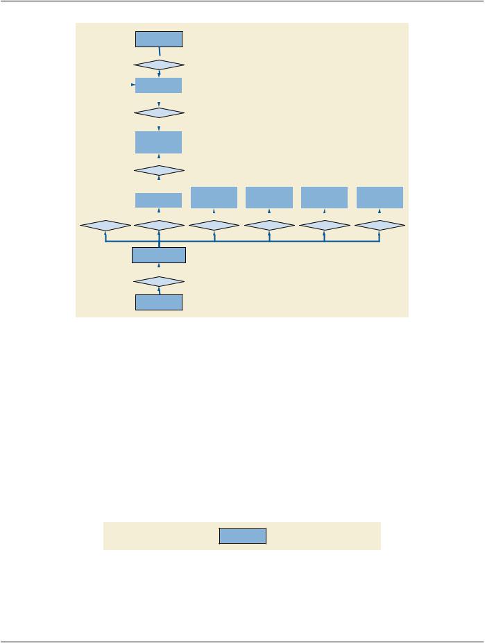
Figure 7.12-2. Display Subsystem Composition in the Display System IOD
Figure 7.12-2 illustrates how the composition of Display Subsystems is represented in the Display System IOD.
7.13 DICOM Model of the Real World for Non-Patient-Related Information
The DICOM Model of the Real World is extended for a variety of non-patient-related information with the specification of entities that are generally separate from the rest of the DICOM Real World Information Model. These information entities are not associated with a specific Patient. While there may be entity relationships, there is no hierarchy applied to these entities.
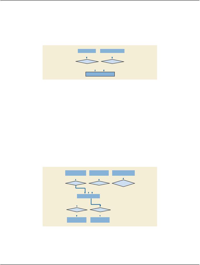
7.13.1 Hanging Protocol Information Entity
A Hanging Protocol Information Entity specifies the viewing preferences of a specific user or group, for a specific type of Study (Modality,Anatomy,Lateralitycombination,andoptionallyProcedure,and/orReason).AHangingProtocoldefinitionincludesdescriptors that identify the Hanging Protocol, the creator, the type of Study it addresses, the type of image sets to display, the intended display environment, and the intended layout for the screen(s).
The Hanging Protocol IE does not have any relationships with other Information Entities. See Figure 7.13-1.
Hanging
Protocol
Figure 7.13-1. DICOM Model of the Real World - Hanging Protocol
- Standard -
DICOM PS3.3 2020a - Information Object Definitions |
Page 127 |
7.13.2 Color Palette Information Entity
A Color Palette Information Entity specifies a color palette suitable for application to an image with a single channel of information (grayscale) to render it in color, i.e., pseudo-coloring.
The Color Palette IE may be referenced by Image or Presentation State Information Entities. See Figure 7.13-2.
The Color Palette IOD instantiates the Color Palette IE only.
Image |
|
Presentation State |
|||
|
|
|
|
|
|
|
0-n |
|
|
|
0-n |
|
|
|
|
||
may reference |
|
|
may reference |
||
|
1-n |
|
|
|
1-n |
|
|
|
|
|
|
|
|
|
|
|
|
Color Palette
Figure 7.13-2. DICOM Model of the Real World - Color Palette
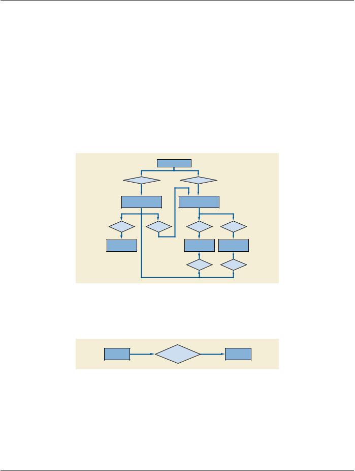
7.13.3 Implant Related Information Entities
7.13.3.1 Implant Template Information Entity
AnImplantTemplateInformationEntityspecifiesa2D-and/or3D-templaterepresentingaphysicalimplant.TheIEspecifiesmechanisms for implant assembly, i.e., the rigid connection of two or more implants.
The Implant Template IE may be related to a Surface IE (see Section A.1.2.18) or to an Encapsulated Document IE (see Sec- tion A.1.2.16) for the specification of the 2Dor 3D-template.
The Implant Template IE may be related to a Frame of Reference IE (see Section A.1.2.5) to support registration of the template with Patient anatomical landmarks in a separate Frame of Reference.
TheImplantTemplateIEmayberelatedtoanImplantAssemblyTemplateIEforthespecificationofmulti-partassemblies.TheImplant Template IE may be related to an Implant Template Group IE for shared management of a set of templates.
See Figure 7.13-3.
Implant Assembly |
|
|
Implant Template |
|
|
Frame of Reference |
||||||||
|
Template |
|
|
|
|
Group |
|
|
||||||
|
|
|
|
|
|
|
|
|
||||||
|
|
|
|
|
|
|
|
|
|
|
|
|
|
|
|
|
|
0-n |
|
|
|
|
|
0-n |
|
|
|
0-n |
|
|
|
|
|
|
|
|
|
|
|
|
||||
|
references |
|
|
|
rerferences |
|
|
spatially defines |
||||||
|
|
|
1-n |
|
|
|
|
|
1-n |
|
|
|
1-n |
|
|
|
|
|
|
|
|
|
|
||||||
|
|
|
|
|
|
|
|
|
|
|
|
|
|
|
|
|
|
|
|
|
|
|
|
|
|
|
|
|
|
|
|
|
|
|
|
|
|
|
||||||
|
|
|
Implant Template |
|
|
|
|
|
||||||
|
|
|
|
|
|
|
|
|
|
|
||||
|
|
|
|
|
|
|
|
|
|
|
|
|
|
|
1 |
|
1 |
|
|
|
|
||||||||
|
contains |
|
|
|
rerferences |
|
|
|
|
|||||
|
|
|
0-n |
|
|
|
|
|
0-n |
|
|
|
|
|
|
|
|
|
|
|
|
|
|
|
|
|
|
|
|
|
|
|
|
|
|
|
|
|
|
|
|
|
|
|
|
Surface |
|
|
|
|
Encapsulated |
|
|
|
|
||||
|
|
|
|
|
Document |
|
|
|
|
|||||
|
|
|
|
|
|
|
|
|
|
|
|
|||
Figure 7.13-3. DICOM Model of the Real World - Implant Templates
7.13.3.2 Implant Assembly Template Information Entity
An Implant Assembly Template Information Entity specifies how to combine several implants to fulfill a certain purpose.
- Standard -
Page 128 |
DICOM PS3.3 2020a - Information Object Definitions |
The Implant Assembly Template IE is related to Implant Template IEs.
7.13.3.3 Implant Template Group Information Entity
An Implant Template Group Information Entity specifies a set of Implant Templates for shared specification and management. It facil- itates browsing through a set of similar implants by providing similar matching coordinates, and by ordering the referenced templates by dimensional size or similar attributes.
The Implant Template Group IE is related to Implant Template IEs.
7.13.4 Extension of The DICOM Model of The Real World For Protocol Storage
The DICOM Model of the Real World is extended with the addition of Defined Procedure Protocol and Performed Procedure Protocol objects whose whose relationship to existing DICOM Real World objects is shown in Figure 7.13.4-1.
Note that the information in the Equipment IE describes the equipment that created the instance. The information in the Protocol Parameters may describe the equipment on which the protocol is intended to be executed which may or may not be the same as the equipment that created the instance.
|
Equipment |
|
|
|
1 |
1 |
|
|
creates |
creates |
|
|
0-n |
0-n |
|
Performed |
Defined |
|
|
Procedure Protocol |
Procedure Protocol |
|
|
1 |
1 |
1 |
1 |
results in |
based on |
references |
defines |
0-n |
0-n |
0-n |
0-n |
Instances |
|
Protocol |
Protocol |
|
Codes |
Parameters |
|
|
|
||
|
|
0-n |
0-n |
|
|
references |
records |
|
|
1 |
1 |
Figure 7.13.4-1. DICOM Model of the Real World - Protocol Storage
7.13.5 Approval Information Entity
An Approval Information Entity describes an approval of an Instance.
Approval |
references |
Instances |
Figure 7.13.5-1. DICOM Model of the Real World - Approval
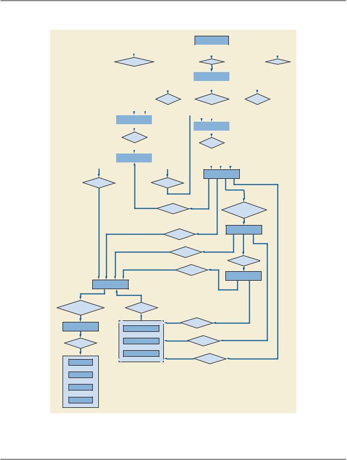
7.14 Extension of The DICOM Model of The Real-world for Radiotherapy Second Generation Information Objects
For the purpose of RT Second Generation SOP Classes the DICOM Model of the Real-World is described in this section. This subset ofthereal-worldmodelcoverstherequirementsfortransferringinformationaboutplannedandperformedradiotherapeutictreatments and associated data.
- Standard -
DICOM PS3.3 2020a - Information Object Definitions |
Page 129 |
Figure 7.14-1 describes the most important elements involved in the radiotherapy domain in DICOM.
Patient
|
|
|
|
|
|
|
|
|
|
|
|
|
|
|
|
|
|
|
|
|
|
|
|
|
|
|
|
|
|
|
|
|
|
|
|
|
|
|
|
|
|
|
|
|
|
1 |
|
|
1 |
||||
|
is subject of |
|
has |
|
has |
||||||||||||
|
|
|
|
|
|
|
|
|
|
|
0-n |
|
|
0-n |
|||
|
|
|
|
|
|
|
|
|
|
|
|
|
|||||
|
|
|
|
|
|
|
|
|
|
|
|
|
|
|
|
|
|
|
|
|
|
|
|
|
|
|
|
RT Course |
|
|
|
|
|||
|
|
|
|
|
|
|
|
|
|
|
|
|
|
|
|
||
|
|
|
|
|
|
|
|
|
|
|
|
|
|
|
|
||
|
|
|
|
|
|
|
|
|
|
|
|
|
|
|
|
|
|
|
|
|
0-1 |
|
|
|
|
|
|
|
0-1 |
|
|||||
|
|
|
|
|
|
references |
subdivided by |
references |
|
||||||||
|
|
|
|
|
|
|
0-n |
|
|
|
|
n |
|
0-n |
|
||
|
|
|
|
|
|
|
|
|
|
|
|
|
|
|
|
|
|
|
|
|
|
|
|
|
|
|
|
|
|
|
|
|
|
|
|
|
|
|
|
|
|
|
|
|
|
|
|
|
|
|
|
|
|
|
RT Physician Intent |
|
|
|
|
|
|
|
|
|
|
|
|
||||
|
|
|
|
|
|
|
|
|
|
|
|
|
|||||
|
|
|
|
1-n |
RT Treatment Phase |
|
|
|
|
||||||||
|
|
|
|
|
|
|
|
|
|
|
|
|
|||||
|
|
|
|
|
|
|
|
|
|
|
|
||||||
|
|
contains |
0-1 |
|
|
|
|
||||||||||
|
|
|
0-n |
|
contains |
|
|
|
|||||||||
|
|
|
|
|
|
|
|
|
|
|
|
0-n |
|
|
|
||
|
|
|
|
|
|
|
|
|
|
|
|
|
|
|
|
|
|
|
|
|
|
|
|
|
|
|
|
|
|
|
|
|
|
|
|
|
RT Prescription |
|
|
|
|
|
|
|
|
|
|
|
|
||||
|
|
|
|
|
|
|
|
|
|
|
|
|
|||||
|
|
|
|
|
|
|
|
|
|
|
|
|
|
|
|
|
|
|
|
|
|
|
|
|
|
|
|
|
|
|
|
|
|
|
|
|
|
|
|
|
|
|
|
|
|
|
|
|
|
|
|
|
|
|
|
|
RT Radiation Set |
|
prescribes to |
prescribes |
|
|
|
|
|
belongs to |
|
constitutes fraction |
|
|
|
|
composed of |
|
|
n |
|
RT Radiation |
|
|
applies to |
|
|
|
|
n |
|
|
|
|
|
n |
|
|
|
applies to |
|
|
|
|
|
n |
|
|
|
|
|
results in |
|
|
|
n |
|
|
|
applies to |
|
|
|
|
|
n |
RT Radiation Record |
|
|
|
|
|
|
Conceptual Volume |
|
|
|
volumetrically |
|
1 |
|
|
calculated for |
|
|
|
|
represented by |
|
|
|
|
|
n |
|
|
|
|
|
|
|
|
RT Segment |
|
defines |
|
|
|
|
|
|
|
Annotation |
RT Dose Histogram |
|
|
|
annotates |
RT Dose Samples |
defines |
|
|
|
|
|
|
|
|
RT Dose Image |
|
|
|
Volumes |
|
|
defines |
|
|
|
|
|
|
or
Surfaces
or
Lines
or
Points
Figure 7.14-1. DICOM Model of the Real World - Radiotherapy
- Standard -

Page 130 |
DICOM PS3.3 2020a - Information Object Definitions |
Note
1.IODswhichcontainarepresentationofVolumes,Surfaces,Lines,PointscanbeannotatedbyanRTSegmentAnnotation.
2.For better readability the diagram only contains the most important relationships, e.g. all objects have a relation to the Patient, but not all of these relationships are part of this diagram.
7.14.1 RT Course
TheRTCourseisatop-levelentitythatrepresentsaradiotherapytreatmentcourse,usuallyspecifiedinoneormoreRTPrescriptions, generally for a defined tumor or group of tumors. A patient undergoing treatments of radiotherapy has one treatment course at a time. The RT Course may consist of several RT Treatment Phases (possibly with breaks of treatment in between them). Each treatment phase may consist of one or more RT Treatment Sessions. An RT Treatment Session is delivered in one patient visit to a venue with a treatment machine and will typically deliver a fraction of one or more RT Radiation Sets. A new RT Course is administered, when the patient is treated for a re-occurrence or a new tumor site - typically after a period of a year or more after the previous RT Course has been finished.
The RT Course can be thought of as a container collecting all major objects which are relevant to this course. The RT Physician Intent andRTRadiationSetsreferenceothercompanionobjectsnecessarytoprepare,conductandreviewthetreatment.Timinginformation (start dates and phasing of treatment, breaks etc.) are also part of the RT Course information. Additionally it contains information of the ongoing status in treatment planning and delivery. The RT Course is a dynamic object that represents the current status of the patient"s treatment.
The RT Course may also include information about previously conducted treatments by referencing previous RT Course objects or by directly recording the information in Attributes.
7.14.2 RT Physician Intent
The RT Physician Intent describes how the physician wishes to achieve curative or palliative therapy. This information includes, but is not limited to the use of external radiation therapy or brachytherapy, total and fractional doses and fractionation schemes, treatment sites, Dosimetric Objectives, envisioned treatment technique, beam energy or isotopes, and patient setup notes.
7.14.3 Conceptual Volume
The Conceptual Volume is a reference to a certain anatomical region or point. Conceptual Volumes may or may not have a repres- entation in segmented images. In most cases they will be related to one or more volumetric representations in various image sets taken at different times.
For example, during a radiotherapy course at the time of prescription, physicians specify regions to which dose is prescribed. Sub- sequently these regions are referenced in other objects in order to track calculated and delivered dose in the course of treatment. This referencing capability is provided by the Conceptual Volume.
7.14.4 RT Segment Annotation
The RT Segment Annotation annotates segmented regions defined in other SOP Instances with radiotherapy-specific information about the role and RT-specific types of the regions (e.g. clinical target volume, organ at risk, bolus) , and other information such as density definitions. An RT Segment Annotation SOP instance may reference any geometric general-purpose representation entity defined by DICOM.
7.14.5 RT Radiation Set
An RT Radiation Set is a collection of RT Radiations. An RT Radiation Set defines a Radiotherapy treatment fraction, which will be applied one or more times. The RT Radiation Set is delivered by delivering the radiation of all referenced RT Radiations.
Parallel and intermittent fractionation schemes, e.g. treatment of several target sites with different timing schemes, are represented by multiple RT Radiation Sets.
7.14.6 RT Radiation
An RT Radiation is a contiguous set of Control Points, describing machine and positioning parameters to be applied during treatment delivery.AnRTRadiationdescribesoneportionofanRTRadiationSetandrepresentsansingle-fractiondeliveryoftherapeuticradiation
- Standard -