Материал: part03
DICOM PS3.3 2020a - Information Object Definitions |
Page 121 |
Clinical Trial |
|
|
|
|
|
Patient |
|
|
|
|
|
|
|||||
Sponsor |
|
|
|
|
|
|
|
|
|
|
|
|
|
|
|||
|
|
|
|
|
|
|
|
|
|
|
|
|
|
|
|
|
|
|
|
|
|
|
|
|
|
|
|
|
|
|
|
|
|
|
|
conducts |
|
|
|
|
|
|
|
|
|
|
|
|
|
||||
|
|
|
|
|
|
|
|
|
|
|
|
|
|
|
|
|
|
|
|
|
|
|
|
|
|
|
|
|
|
|
|
|
|
|
|
|
|
|
|
|
|
|
|
|
|
|
|
|
|
|
|||
Clinical Trial |
|
|
|
|
|
|
|
|
|
|
|
|
|
|
|||
Protocol |
|
|
|
|
|
|
|
|
|
|
|
Clinical Trial |
|||||
|
|
|
|
|
|
|
|
|
|
|
|
|
|
|
Time Point |
||
|
|
|
|
|
|
|
|
|
|
|
|
|
|
|
|||
|
|
|
|
|
|
|
|
|
|
|
|
|
|
|
|
|
|
|
|
|
|
|
|
|
|
|
|
|
|
|
|
|
|
|
|
|
|
|
|
|
|
|
|
|
|
|
|
|
0-1 |
||||
involves |
identified as |
|
|
has |
|
|
contains |
||||||||||
|
|
|
|
|
|
|
|
|
|
|
|
|
|
|
|
|
1-n |
|
|
|
|
|
|
|
|
|
|
|
|
|
|
|
|
|
|
|
|
|
|
|
|
|
|
|
|
|
|
|
|
|
|
|
|
|
|
Clinical Trial |
|
|
|
|
|
|
|
|
Study |
|
|
||||
|
|
Subject |
|
|
|
|
|
|
|
|
|
||||||
|
|
|
|
|
|
|
|
|
|
|
|
|
|
|
|||
|
|
|
|
|
1-n |
|
|
|
|
|
|
|
|
|
|
||
|
|
|
|
|
|
|
|
|
|
|
|
|
|
||||
|
|
located at |
|
|
|
|
|
|
|
|
contains |
||||||
|
|
|
|
|
1 |
|
|
|
|
|
|
|
|
|
|
|
|
|
|
|
|
|
|
|
|
|
|
|
|
|
|
|
|
|
|
|
|
|
|
|
|
|
|
|
|
|
|||||||
|
|
Clinical Trial Site |
|
|
|
|
|
|
|
Series |
|
||||||
|
|
|
|
|
|
|
|
|
|
|
|
|
|
|
|
|
|
|
|
|
|
|
|
|
|
|
|
|
|
|
|
|
|
|
|
|
|
|
|
|
|
|
|
|
|
|
|
|
submitted to |
||||
|
|
|
|
|
|
|
|
|
|
|
|
|
|
|
|
|
|
|
|
|
|
|
|
|
|
|
|
|
|
|
|
|
|
|
|
|
|
|
|
|
|
|
|
|
|
|
|
|
|
|
|||
|
|
|
|
|
|
|
|
|
|
|
|
|
Clinical Trial |
|
|
||
|
|
|
|
|
|
|
|
|
|
|
|
|
Coord. Center |
|
|||
|
|
|
|
|
|
|
|
|
|
|
|
|
|
|
|
|
|
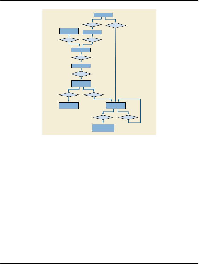
Figure 7.6-1. DICOM Model of the Real World - Clinical Trials and Research
7.6.1 Clinical Trial and Research Information Entities
For the purpose of Clinical Trial and Research Information, an extension of the DICOM Model of the Real World is made, as depicted
in Figure 7.6-1.
7.6.1.1 Clinical Trial Sponsor
AClinicalTrialSponsoridentifiestheagency,group,orinstitutionresponsibleforconductingand/orfundingtheclinicaltrialorresearch, and for assigning a Protocol Identifier.
7.6.1.2 Clinical Trial Protocol
A Clinical Trial Protocol identifies the investigational Protocol in which the Subject has been enrolled. The Protocol has a Protocol Identifier and Protocol Name, as well as information related to Ethics Committee, Institutional Review Board (IRB) or Institutional Animal Care and Use Committees (IACUC) approval.
7.6.1.3 Clinical Trial Subject
A Clinical Trial Subject identifies the Patient who is enrolled as a Subject in the investigational Protocol.
7.6.1.4 Clinical Trial Site
A Clinical Trial Site identifies the location or institutionat which the Subject is treated or evaluated and that is responsible for submitting clinical trial or research data. Images and/or clinical trial data may be collected for a given Subject at alternate institutions, e.g., follow- up scans at a satellite imaging center, but the Clinical Trial Site represents the primary location for Patient management and data submission in the context of a clinical trial or research. In pre-clinical research with small animals, it is typically the single laboratory or shared resource facility.
- Standard -

Page 122 |
DICOM PS3.3 2020a - Information Object Definitions |
7.6.1.5 Clinical Trial Time Point
The Clinical Trial Time Point identifies an imaging Study within the context of a series of longitudinal data acquisitions in an investig- ational protocol. A Time Point defines a set of Studies that are grouped together as a clinical time point or submission in a clinical trial or for other research.
7.6.1.6 Clinical Trial Coordinating Center
The Clinical Trial Coordinating Center identifies the institution responsible for coordinating the collection, management, processing, and/or analysis of images and associated data for Subjects enrolled in a clinical trial or research. Within a given Clinical Trial Protocol, there may be multiple Clinical Trial Coordinating Centers, each handling different aspects of the clinical data submitted by the Clinical Trial Sites. In pre-clinical research with small animals, it may be a facility where post processing is performed, separate from the laboratory where the data is acquired.
7.7 Extension of the DICOM Model of the Real World for Hanging Protocols
See Section 7.13.
Note
The specifications of this section have been consolidated into the Real World Model for Non-Patient-Related Information.
7.8 Extension of the DICOM Model of the Real World for Color Palettes
See Section 7.13.
Note
The specifications of this section have been consolidated into the Real World Model for Non-Patient-Related Information.
7.9 Extension of the DICOM Model of the Real World for Specimens
The DICOM Model of the Real World is extended for Specimens with the addition of several objects whose relationships to each other and existing DICOM Real World objects are shown in Figure 7.9-1.
Attributes of the Specimen, Container, Component and Preparation Step objects are represented in the Specimen Module within the Image IODs.
- Standard -
DICOM PS3.3 2020a - Information Object Definitions |
Page 123 |
Patient
1 |
1 |
|
has |
is source of |
|
1-n |
||
1-n |
||
|
Equipment
Modality Study
1 |
1 |
creates |
contains |
1-n |
1-n |
Series |
|
|
|
1 |
|
contains |
|
|
1-n |
|
|
Image |
|
|
|
1 |
|
is acquired on |
|
|
|
1 |
|
Container |
|
|
Box, Block, Slide, etc. |
|
|
1 |
1 |
|
has |
contains |
|
1-n |
1-n |
|
Component |
Specimen |
|
Base, Coverslip |
Physical Object |
|
|
1 |
1 |
|
has |
is child of |
|
1-n |
1-n |
|
Preparation Step |
|
|
Collect, Sample, |
|
|
Stain, Process |
|
Figure 7.9-1. DICOM Model of the Real World - Specimens
7.9.1 Specimen
A physical object (or a collection of objects) is a specimen when the laboratory considers it a single discrete, uniquely identified unit that is the subject of one or more steps in the laboratory (diagnostic) workflow.
7.9.2 Container
Specimen containers (or just "containers") play an important role in laboratory (diagnostic) processes. In most, but not all, process steps, specimens are held in containers, and a container often carries its specimen's ID. Sometimes the container becomes intimately involved with the specimen (e.g., a paraffin block), and in some situations (such as examining tissue under the microscope) the con- tainer (the slide and coverslip) become part of the optical path.
7.9.3 Container Component
Containers are often made up of components. For example, a "slide" is container that is made up of the glass slide, the coverslip and the "glue" the binds them together.
7.9.4 Preparation Step
Before a slide is imaged, the preparation of the specimen (including sampling, processing and staining) will take place. Specimen preparation is described as a sequence of time-stamped process steps. Multiple steps are possible, and may include sampling from ancestor specimens.
- Standard -
Page 124 |
DICOM PS3.3 2020a - Information Object Definitions |
7.10 Extension of DICOM Model of the Real World for Implant Templates
See Section 7.13.
Note
The specifications of this section have been consolidated into the Real World Model for Non-Patient-Related Information.
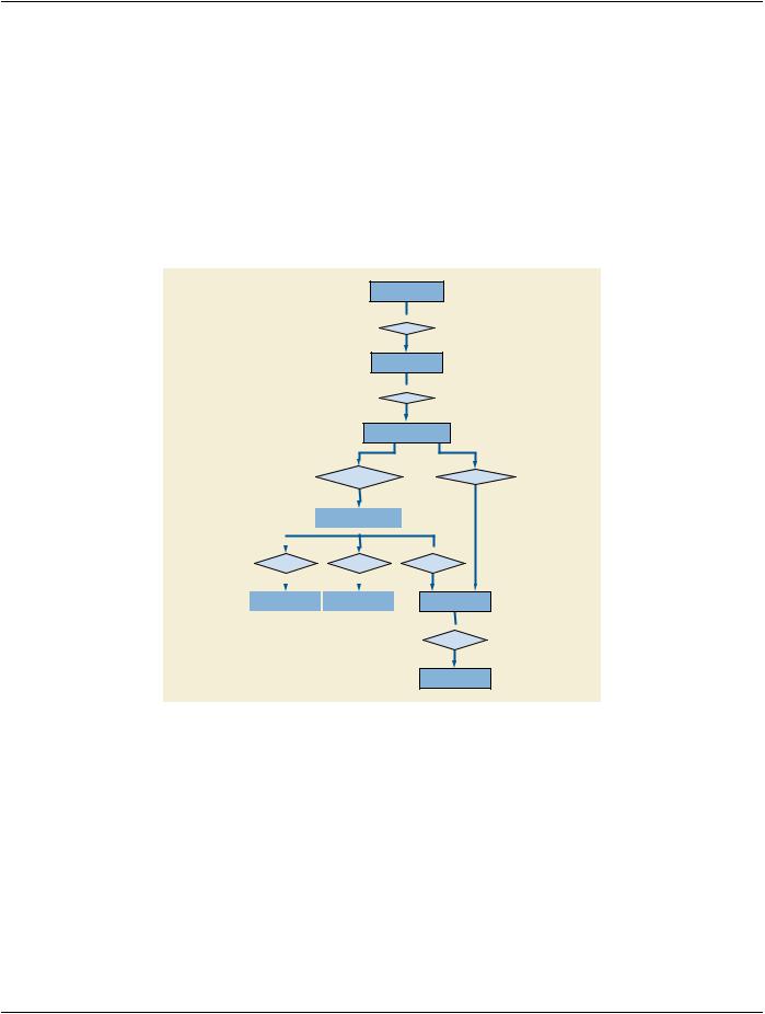
7.11 Extension of the DICOM Model of the Real World for the Unified Procedure Step (UPS)
The DICOM Model of the Real World is extended with the addition of a Unified Procedure Step object whose relationship to existing DICOM Real World objects is shown in Figure 7.11-1.
Patient
 1 has
1 has
0-n
Service Request
 1 has
1 has
1-n
Requested Procedure
0-n
|
|
|
is comprised of |
||
|
|
|
|
|
|
|
|
|
Unified |
||
|
|
|
Procedure Step |
||
|
|
|
|
|
|
|
0-n |
1 |
|
||
|
|
||||
belongs to |
references |
||||
|
1 |
|
0-n |
||
|
|
|
|
|
|
|
|
|
|
|
|
Worklist |
Composite |
|
|||
Objects |
|
||||
|
|
|
|
||
results in
0-n
 1 results in
0-n
Series
 1 has
1 has
0-n
Composite
Objects
Figure 7.11-1. DICOM Model of the Real World - Unified Procedure Step
7.11.1 Unified Procedure Step
A Unified Procedure Step (UPS) represents an arbitrary unit of service. Unified Procedure Steps are generally scheduled in response to a Requested Procedure, although a UPS may be triggered by other events, such as a scheduled calibration, completion of prior work in a pipeline, etc.
The Unified Procedure Step (UPS) unifies the details of the procedure step that has been requested, the progress details during performance, and the details of the procedure step actually performed. The details can describe the specific service activity, the subject and/or data acted on, the originator and context of the request, the human/equipment/application resources involved, the priority, date, time and location of the activity, and references to resulting output data.
Normallythedetailsabouttheactivityasperformedcorrespondtothedetailsoftheactivityasrequested,howeverreal-worldconditions may dictate that what is actually performed does not correspond exactly with what was requested or scheduled.
- Standard -
DICOM PS3.3 2020a - Information Object Definitions |
Page 125 |
7.11.2 Worklist
A Worklist is an arbitrary collection of Unified Procedure Steps that share a common worklist label.
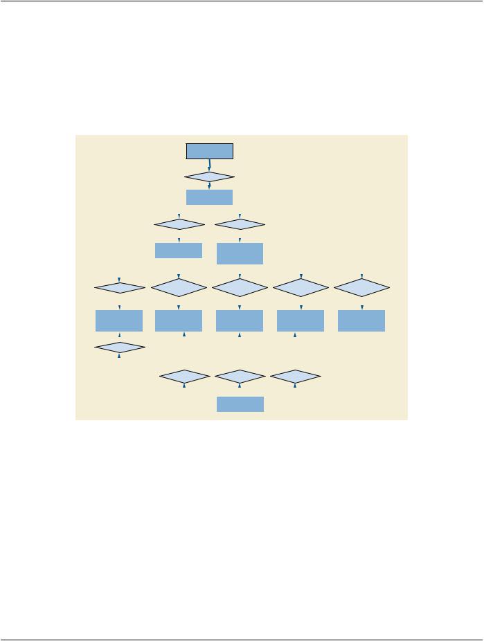
7.12 Extension of The DICOM Model of The Real World For Display System
The DICOM Model of the Real World is extended for Display System with the addition of an entity that is separate from the rest of the DICOM Real World objects, as shown in Figure 7.12-1. A Display System is not associated with any specific objects in the existing DICOM Information model, because it is not associated with a specific Patient. One Display System object is included in a Display System IOD.
Display
System
|
|
|
|
|
|
|
|
|
|
|
|
has |
1 |
|
|
|
|
|
|
|
|
|
|
|
|
|
|
|
|
|
|
|
|
|
|
|
|
|
|
|
|
|
|
|
|
|
|
||
|
|
|
|
|
|
|
|
|
|
|
|
|
|
1-n |
|
|
|
|
|
|
|
|||
|
|
|
|
|
|
|
|
|
|
|
|
|
|
|
|
|
|
|
|
|
|
|
|
|
|
|
|
|
|
|
|
|
|
|
Display |
|
|
|
|
|
|
|
|
|
|
||||
|
|
|
|
|
|
|
|
|
|
Subsystem |
|
|
|
|
|
|
|
|
|
|
||||
|
|
|
|
|
|
|
|
|
|
|
|
|
|
|
|
|
|
|
|
|
|
|
|
|
|
|
|
|
|
|
|
|
|
|
|
|
|
|
|
|
|
|
|
|
|
|
|
|
|
|
|
|
|
|
|
1 |
|
|
|
1 |
|
|
|
|
|
|
|
|||||||
|
|
|
|
|
|
consists of |
|
has |
|
|
|
|
|
|
|
|||||||||
|
|
|
|
|
|
|
|
|
1 |
|
|
|
|
|
|
1-n |
|
|
|
|
|
|
|
|
|
|
|
|
|
|
|
|
|
|
|
|
|
|
|
|
|
|
|
||||||
|
|
|
|
|
|
|
|
|
|
|
|
|
|
|
|
|
|
|
|
|
|
|
|
|
|
|
|
|
|
|
|
|
|
|
|
|
|
|
|
|
|
|
|
|
|
|
|
|
|
|
|
|
|
|
|
Display |
|
|
Display |
|
|
|
|
|
|
|
||||||||
|
|
|
|
|
|
Device |
|
Subsystem |
|
|
|
|
|
|
|
|||||||||
|
|
|
|
|
|
|
|
|
|
|
|
|
|
Configuration |
|
|
|
|
|
|
|
|||
|
|
|
|
|
|
|
|
|
|
|
|
|
|
|
|
|
|
|
|
|
||||
|
|
|
|
|
|
|
|
|
|
|
|
|
|
|
|
|
|
|
|
|
|
|
||
|
|
|
|
|
|
|
|
|
|
|
|
|
|
|
|
|
|
|
|
|
|
|
|
|
|
|
|
1 |
|
1 |
|
|
|
1 |
1 |
1 |
|||||||||||||
|
|
|
|
|||||||||||||||||||||
defines |
is evaluated |
is evaluated |
|
is evaluated |
|
is evaluated |
||||||||||||||||||
in terms of |
in terms of |
|
in terms of |
|
in terms of |
|||||||||||||||||||
|
|
|
|
1 |
|
|
|
|||||||||||||||||
|
|
|
|
|
0-1 |
|
|
|
|
0-1 |
|
|
0-1 |
|
|
0-1 |
||||||||
|
|
|
|
|
|
|
|
|
|
|
|
|
|
|
|
|
|
|||||||
|
|
|
|
|
|
|
|
|
|
|
|
|
|
|
|
|
|
|
|
|
|
|
|
|
Target |
|
Display |
|
|
|
Luminance |
|
Luminance |
|
Visual |
||||||||||||||
Luminance |
|
Calibration |
|
|
|
|
Uniformity |
|
Evaluation |
|||||||||||||||
|
|
Result |
|
|
||||||||||||||||||||
Characteristics |
|
|
Result |
|
|
|
|
Result |
|
Result |
||||||||||||||
|
|
|
|
|
|
|
|
|
||||||||||||||||
|
|
|
|
1 |
|
|
|
|
|
|
|
|
|
|
|
|
|
|
|
|
|
|
|
|
|
|
|
|
|
|
|
|
|
|
|
|
|
|
|
|
|
|
|
|
|
|
|||
|
|
|
|
|
|
|
|
|
|
|
|
|
|
|
|
|
|
|
|
|||||
targeted |
|
|
|
|
|
|
|
|
|
|
|
|
|
|
|
|
|
|
|
|||||
1 |
|
|
|
|
|
|
|
|
|
|
|
|
|
|
|
|
|
|
|
|
||||
|
|
|
|
|
|
|
|
|
|
1 |
|
|
|
|
1 |
|
|
1 |
|
|
|
|||
|
|
|
|
|
|
|
|
|
|
|
|
|
|
|
|
|
||||||||
|
|
|
|
|
|
|
|
|
|
|
|
|
|
|
|
|
||||||||
|
|
|
|
|
|
|
measures |
measures |
|
measures |
|
|
|
|||||||||||
|
|
|
|
|
|
|
|
|
|
1-n |
|
|
|
1-n |
|
|
|
1-n |
|
|
|
|||
|
|
|
|
|
|
|
|
|
|
|
|
|
|
|
|
|
|
|
|
|
|
|
|
|
|
|
|
|
|
|
|
|
|
|
|
|
|
|
|
|
|
|
|
|
|
|
|
|
|
|
|
|
|
|
|
|
|
|
|
|
|
|
|
|
|
|
|
|
|
|
|
|
|
|
|
|
|
|
|
|
|
|
|
|
|
|
|
|
Measurement |
|
|
|
|
|
|
|
|||
|
|
|
|
|
|
|
|
|
|
|
|
|
|
Equipment |
|
|
|
|
|
|
|
|||
Figure 7.12-1. DICOM Model of the Real World - Display System
A Display Subsystem represents the target of a Display QA task such as calibration. For example, a PACS reading station with one color controller driving one display, and 4 grayscale displays each driven by two controllers is modeled as 5 Display Subsystems, each of which can be the target of a Display QA task. A tablet represents one Display System with a Display Device but no externally exposed controller. Although Display Subsystem may include components beyond the Display Device, this Model focuses on the Display Device only.
- Standard -