Материал: part03

Внимание! Если размещение файла нарушает Ваши авторские права, то обязательно сообщите нам

Page 916​

DICOM PS3.3 2020a - Information Object Definitions​

Note​

1.​The Label of the Slide is presumed to be mounted-on or written-on the Top Surface of the Slide.​

2.​Specification of the mechanical form, function, or tolerances of the Microscope are outside the scope of this Standard.​

Figure C.8-16 depicts the Top Surface of the Slide on the Microscope Stage from the perspective of the Objective Lens. This is Ref-​ erence Slide Orientation. The X, Y, and Z axes of the Slide Coordinate System in Reference Slide Orientation are defined as follows.​ The Y-axis is a line that nominally represents the Left Edge of the Slide. The X-axis is a line that is orthogonal to the Y-axis and​ nominally represents the Specimen Edge of the Slide. The Z-axis is a line that passes through the intersection of the X-axis and Y-​ axis and is orthogonal to the Microscope Stage. The Origin (0,0,0) of the Slide Coordinate System is the point of intersection of the​ X, Y, and Z axes.​

Microscope Stage

Y


Label


Edge


Label

Left

Right

Edge

Edge

Glass Slide


Substrate


Specimen


Origin

X


Specimen


Edge

Figure C.8-16. Reference Slide Orientation​

Note​

1.​An improperly-placed coverslip or Specimen that overlaps an Edge of a Slide is not considered part of the Edge a Slide​ for purposes of defining the Slide Coordinate System. However, such objects may cause inaccurate positioning of the​ Slide on the Stage.​

2.​If the Left Edge and Specimen Edge of the Slide are not orthogonal (e.g., the Slide is damaged or defective or the​ Specimen Edge is curvilinear), then the lower left-hand corner of the Slide may not be located at the Origin.​

3.​The definitions of X, Y, and Z axes are the same for inverted microscopes, with the Top Surface of the slide (i.e., Spe-​ cimen side of the Slide) still being closest to the Objective Lens.​

4.​The origin of a Frame of Reference is arbitrary (see Section C.7.4.1), but its nominal location for consistency of slide​ coordinates is defined in this section.​

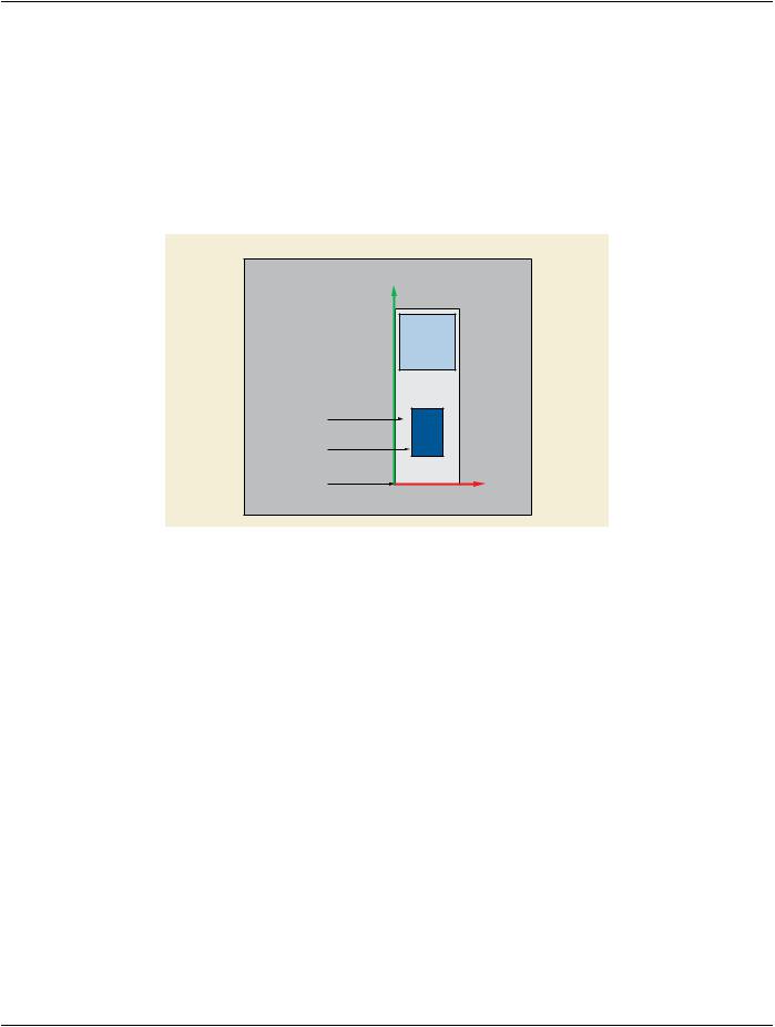
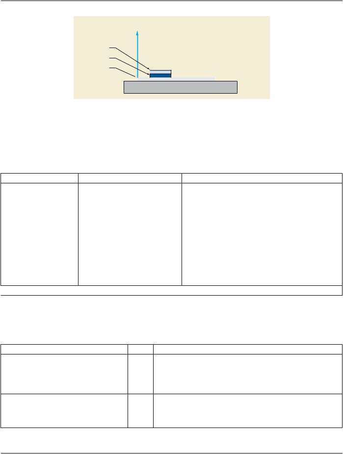
Figure C.8-17 depicts the Z-axis center point location. The X Offset in Slide Coordinate System (0040,072A) shall increase from the​ Origin toward the Right Edge in Reference Slide Orientation. The Y Offset in Slide Coordinate System (0040,073A) shall increase​ from the Origin toward the Label Edge in Reference Slide Orientation. The Z Offset in Slide Coordinate System (0040,074A) shall be​ nominally referenced as zero at the image substrate reference plane (i.e., the top surface of a glass slide) and shall increase in a​ positive fashion coincident with increased distance from the substrate surface.​

- Standard -​

DICOM PS3.3 2020a - Information Object Definitions​

Page 917​

Z

Cover Slip

Specimen

Origin

Glass Slide Y

Substrate

Microscope Stage

Figure C.8-17. Z-Axis Center Point Location, View From Right Edge of Slide​

C.8.12.3 Whole Slide Microscopy Series Module​

Table C.8.12.3-1 specifies Attributes for the Whole Slide Microscopy Series Module, including specialization of Attributes in the​ General Series Module for use in the Whole Slide Microscopy Series Module.​

Table C.8.12.3-1. Whole Slide Microscopy Series Module Attributes​

Attribute Name​

Tag​

Type​

Attribute Description​

Modality​

(0008,0060)​

1​

Type of equipment that originally acquired the data used to​


create the images in this Series.​


Enumerated Values:​


SM​


See Section C.7.3.1.1.1 for further explanation.​

Referenced Performed​

(0008,1111)​

1C​

Uniquely identifies the Performed Procedure Step SOP​

Procedure Step Sequence​


Instance to which the Series is related.​

Only a single Item shall be included in this Sequence.​

Required if a Performed Procedure Step SOP Class was​ involved in the creation of this Series.​

>Include Table 10-11 “SOP Instance Reference Macro Attributes”​

C.8.12.4 Whole Slide Microscopy Image Module​

Table C.8.12.4-1 specifies the Attributes that describe the Whole Slide Microscopy Image Module.​

Table C.8.12.4-1. Whole Slide Microscopy Image Module Attributes​

Attribute Name​

Tag​

Type​

Attribute Description​

Image Type​

(0008,0008)​

1​

Image identification characteristics.​


See Section C.8.12.4.1.1 for specialization.​

Imaged Volume Width​

(0048,0001)​

1​ Width of total imaged volume (distance in the direction of rows in each​


frame) in mm. See Section C.8.12.4.1.2​

Imaged Volume Height​

(0048,0002)​

1​ Height of total imaged volume (distance in the direction of columns in​


each frame) in mm. See Section C.8.12.4.1.2​

Imaged Volume Depth​

(0048,0003)​

1​ Depth of total imaged volume (distance in the Z direction of focal planes)​


in µm. See Section C.8.12.4.1.2​

- Standard -​

Page 918​

DICOM PS3.3 2020a - Information Object Definitions​

Attribute Name​

Tag​

Type​

Attribute Description​

Total Pixel Matrix Columns​

(0048,0006)​

1​

Totalnumberofcolumnsinpixelmatrix;i.e.,widthoftotalimagedvolume​


in pixels. See Section C.8.12.4.1.3​

Total Pixel Matrix Rows​

(0048,0007)​

1​

Total number of rows in pixel matrix; i.e., height of total imaged volume​


in pixels. See Section C.8.12.4.1.3​

Total Pixel Matrix Focal​

(0048,0303)​

1C​

Total number of focal planes (Z locations) in the pixel matrix; i.e., depth​

Planes​


of total imaged volume in pixels. See Section C.8.12.4.1.3​


Required if Dimension Organization Type (0020,9311) is present with a​


value of TILED_FULL. May be present otherwise.​


Note​


Total Pixel Matrix Focal Planes (0048,0303) describes the​


number of focal planes separately encoded, and is distinct from​


Number of Focal Planes (0048,0013), which describes in what​


manner different focal planes were combined into a single​


encoded plane (focus stacking).​

Total Pixel Matrix Origin​

(0048,0008)​

1​

Locationofpixel1\1ofthetotalpixelmatrixintheSlideCoordinateSystem​

Sequence​


Frame of Reference.​


Only a single Item shall be included in this Sequence.​


SeeSectionC.8.12.4.1.4andSectionC.8.12.2.1.1forfurtherexplanation​

>X Offset in Slide​

(0040,072A)​

1​

TheXoffsetinmillimetersfromtheOriginoftheSlideCoordinateSystem.​

Coordinate System​


>Y Offset in Slide​

(0040,073A)​

1​

TheYoffsetinmillimetersfromtheOriginoftheSlideCoordinateSystem.​

Coordinate System​


Image Orientation (Slide)​

(0048,0102)​

1​

The direction cosines of the first row and the first column of the total pixel​


matrix with respect to the Slide Coordinate System Frame of Reference.​


See Section C.8.12.4.1.4​

Samples Per Pixel​

(0028,0002)​

1​

Number of samples (color planes) per frame in this image.​


Enumerated Values:​


3​


1​


See Section C.8.12.4.1.5 for further explanation.​

Photometric Interpretation​

(0028,0004)​

1​

Specifies the intended interpretation of the pixel data.​


See Section C.8.12.4.1.5 for Enumerated Values.​

Planar Configuration​

(0028,0006)​

1C​

Indicates whether the pixel data are encoded color-by-plane or​


color-by-pixel. Required if Samples per Pixel (0028,0002) has a value​


greater than 1.​


Enumerated Values:​


0​color-by-pixel​

Number of Frames​

(0028,0008)​

1​

Number of frames in a multi-frame image.​


Enumerated Values if Image Type (0008,0008) Value 3 is LOCALIZER​


or LABEL:​


1​

- Standard -​


DICOM PS3.3 2020a - Information Object Definitions​

Page 919​

Attribute Name​

Tag​

Type​

Attribute Description​


Bits Allocated​

(0028,0100)​

1​

Number of bits allocated for each pixel sample.​


Enumerated Values:​


8​


16​


Bits Stored​

(0028,0101)​

1​

Number of bits stored for each pixel sample. Shall be equal to Bits​


Allocated (0028,0100).​


High Bit​

(0028,0102)​

1​

Most significant bit for pixel sample data. High Bit (0028,0102) shall be​


one less than Bits Stored (0028,0101).​


Pixel Representation​

(0028,0103)​

1​

Data representation of pixel samples.​


Enumerated Values:​


0​unsigned integer​


Acquisition DateTime​

(0008,002A)​

1​

The date and time that the acquisition of data that resulted in this image​


started.​


Acquisition Duration​

(0018,9073)​

3​

Duration of the image acquisition in seconds.​


Lossy Image Compression​

(0028,2110)​

1​

SpecifieswhetheranImagehasundergonelossycompression(atapoint​


in its lifetime).​


Enumerated Values:​


00​Image has NOT been subjected to lossy compression.​


01​Image has been subjected to lossy compression.​


Once this value has been set to 01 it shall not be reset.​


See Section C.7.6.1.1.5​


Lossy Image Compression​

(0028,2112)​

1C​

Describes the approximate lossy compression ratio(s) that have been​

Ratio​


applied to this image.​


See Section C.7.6.1.1.5.2.​


Required if Lossy Image Compression (0028,2110) is "01".​


Lossy Image Compression​

(0028,2114)​

1C​

A label for the lossy compression method(s) that have been applied to​

Method​


this image.​


See Section C.7.6.1.1.5.1.​


Required if Lossy Image Compression (0028,2110) is "01".​


Presentation LUT Shape​

(2050,0020)​

1C​

Specifies an identity transformation for the Presentation LUT, such that​


the output of all grayscale transformations defined in the IOD containing​


this Module are defined to be P-Values.​


Enumerated Values:​

IDENTITY​ output is in P-Values.​

Required if Photometric Interpretation (0028,0004) is MONOCHROME2.​

- Standard -​

Page 920​

DICOM PS3.3 2020a - Information Object Definitions​

Attribute Name​

Tag​

Type​

Attribute Description​

Rescale Intercept​

(0028,1052)​

1C​

The value b in relationship between stored values (SV) and the output​


units.​


Output units = m*SV + b.​


Required if Photometric Interpretation (0028,0004) is MONOCHROME2.​


Enumerated Values:​


0​

Rescale Slope​

(0028,1053)​

1C​

m in the equation specified by Rescale Intercept (0028,1052).​


Required if Photometric Interpretation (0028,0004) is MONOCHROME2.​


Enumerated Values:​


1​

Volumetric Properties​

(0008,9206)​

1​

IndicationifgeometricmanipulationsarepossiblewithframesintheSOP​


Instance. See Section C.8.16.2.1.2.​


Enumerated Values:​


VOLUME​pixels represent the volume specified for the image, and may​


be geometrically manipulated​

Specimen Label in Image​

(0048,0010)​

1​

Indicates whether the specimen label is captured in the image.​


Enumerated Values:​


YES​


NO​

Burned In Annotation​

(0028,0301)​

1​

Indicates whether or not image contains sufficient burned in annotation​


to identify the patient.​


Enumerated Values:​


YES​


NO​


Note​


If Specimen Label in Image (0048,0010) value is YES, Burned​


InAnnotation(0028,0301)mightbeNOifthelabelincludesonly​


a specimen identifier and not patient identifying data.​

Focus Method​

(0048,0011)​

1​

Method of focusing image​


Enumerated Values:​


AUTO​ autofocus​


MANUAL​includes any human adjustment or verification of autofocus​

Extended Depth of Field​

(0048,0012)​

1​

Image pixels were created through combining of image acquisition at​


multiple focal planes (focus stacking).​

Enumerated Values:​

YES​

NO​

- Standard -​