Материал: part03

Внимание! Если размещение файла нарушает Ваши авторские права, то обязательно сообщите нам

Page 906​

DICOM PS3.3 2020a - Information Object Definitions​


Enumerated Value​

Definition​

ACR MQCM​


Equivalent​

POSTFIRE_PLUS​

The paired image obtained with the X-Ray source angle increased from the​…POF+​


scout position, with the biopsy needle in position following needle deployment​


through the targeted lesion.​


POSTBIOPSY_MINUS​

The image obtained following tissue acquisition with the X-Ray source angle​…POB-​


decreased from the scout position.​


POSTBIOPSY_PLUS​

The image obtained following tissue acquisition with the X-Ray source angle​…POB+​


increased from the scout position.​


POSTBIOPSY​

The image obtained following tissue acquisition with the X-Ray source in the​…POB​


scout position.​


POSTMARKER_MINUS​

The image obtained following micromarker placement with the X-Ray source​…POM-​


angle decreased from the scout position.​


POSTMARKER_PLUS​

The image obtained following micromarker placement with the X-Ray source​…POM+​


angle increased from the scout position.​


POSTMARKER​

The image obtained following micromarker placement with the X-Ray source​…POM​


in the scout position.​


The Enumerated Values for Value 3 of digital breast tomosynthesis projection images and mathematically generated 2D images are:​

Table C.8-74b. Enumerated Values of Image Type (0008,0008) Value 3 for Digital Breast Tomosynthesis​ Projection and Generated 2D Images​

Enumerated Value​

Definition​

ACR MQCM​


Equivalent​

TOMO_PROJ​

Identifies the image as a digital breast tomosynthesis projection image.​

n/a​

TOMOSYNTHESIS​

Identifies the image as digital breast tomosynthesis; shall be used only for​n/a​


generated 2D images when no other Value 3 takes precedence.​


TOMO_SCOUT​

A localizer image that may be used to determine positioning coordinates​ …SC​


prior to needle positioning.​


PREFIRE​

The image obtained with the biopsy needle in position prior to needle​

…PRF​


deployment.​


POSTFIRE​

The image obtained with the biopsy needle in position following needle​

…POF​


deployment through the targeted lesion.​


POSTBIOPSY​

The image obtained following tissue acquisition with the X-Ray source in​…POB​


the scout position.​


POSTMARKER​

TheimageobtainedfollowingmicromarkerplacementwiththeX-Raysource​…POM​


in the scout position.​


Note​

Digital breast tomosynthesis projection images acquired as part of a biopsy procedure (and resulting derived images such​ as mathematically generated 2D) omit the _MINUS and _PLUS endings because a single digital breast tomosynthesis ac-​ quisition produces a set of projection images that replaces the _MINUS and _PLUS image pair used in conventional 2D​ breast biopsy imaging.​

The Enumerated Values for Value 3 of contrast enhanced images are:​

Table C.8-74c. Enumerated Values of Image Type (0008,0008) Value 3 for Contrast Enhanced Images​

Enumerated Value​

Definition​

PRE_CONTRAST​

Collected before contrast was administered.​

POST_CONTRAST​

Collected during or after contrast was administered.​

- Standard -​

DICOM PS3.3 2020a - Information Object Definitions​

Page 907​

Ifmorethanonecharacteristic(biopsy,tomosynthesis,contrastenhanced)appliestoanimage,Value3shallcontainthebiopsyimage​ type. If biopsy is not involved, Value 3 shall contain the tomosynthesis image type.​

Note​

For example, Attributes of the Contrast/Bolus Module may be used to identify contrast enhanced characteristics of a biopsy​ and/or tomosynthesis projection or generated 2D image that is also contrast enhanced.​

Value 4 shall be present for images acquired using contrast enhanced digital X-Ray imaging of the breast (but may be empty if none​ of the Defined Terms applies), and for mathematically generated 2D images. For other images Value 4 remains optional and imple-​ mentation specific.​

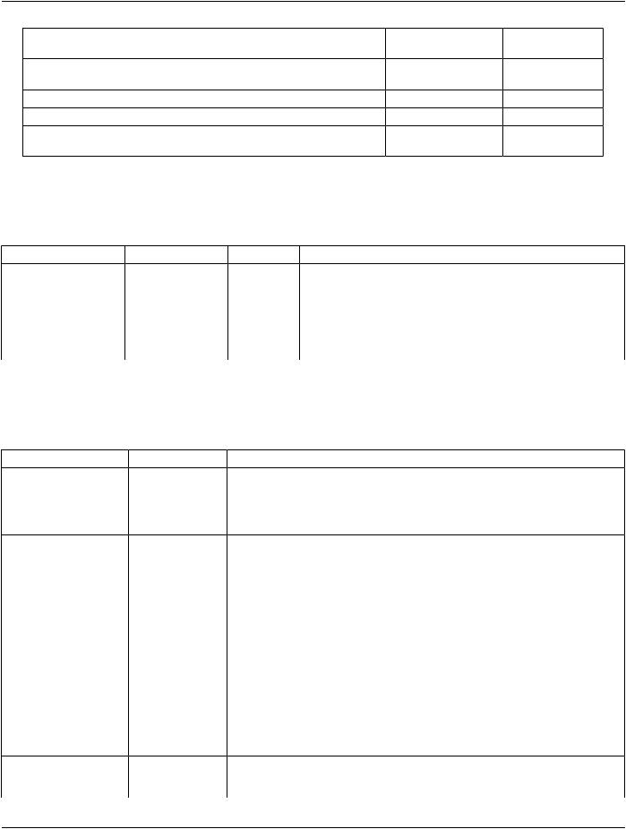
Table C.8-74d. Defined Terms of Image Type (0008,0008) Value 4 for Contrast Enhanced and Generated​ 2D Images​

Enumerated Value​

Definition​

GENERATED_2D​

Mathematically generated 2D view.​

ADDITION​

Created through Pixel by pixel addition operation.​

SUBTRACTION​

Created through Pixel by pixel subtraction operation.​

If more than one characteristic (contrast enhanced, tomosynthesis) applies to an image, Value 4 shall contain the contrast enhanced​ image type. If contrast enhanced is not involved, Value 4 shall contain the generated 2D image type.​

Value 5 shall be present for images acquired using contrast enhanced digital X-Ray imaging of the breast, but may be empty if none​ of the Defined Terms applies. For non-contrast images Value 5 remains optional and implementation specific.​

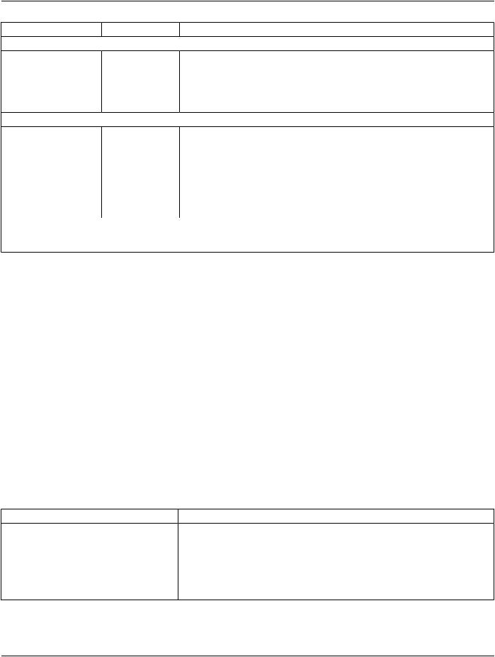
Table C.8-74e. Defined Terms of Image Type (0008,0008) Value 5 for Contrast Enhanced 2D Images​

Enumerated Value​

Definition​

LOW_ENERGY​

Low energy image.​

HIGH_ENERGY​

High energy image.​

Note​


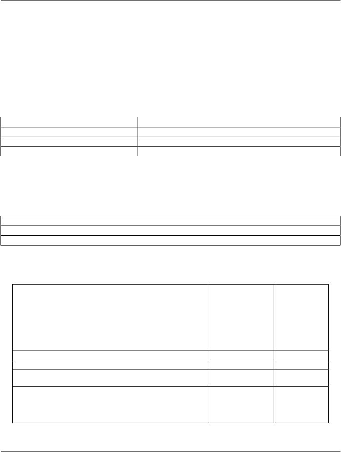
A recipient may use the different values for biopsy, tomosynthesis and contrast views to determine how to display them, for​ example in hanging protocols:​


Image Type Value 3​

Image Type Value 4​ Image Type Value​


5​

Conventional 2D mammography​

empty​

-​

-​

Stereotactic post-biopsy​

POSTBIOPSY​

-​

-​

Pre-contrast 2D​

PRE_CONTRAST​

empty​

empty​

Post-contrast 2D low energy​

POST_CONTRAST​

-​

LOW_ENERGY​

Post-contrast 2D addition​

POST_CONTRAST​

ADDITION​

empty​

Stereotactic scout pre-contrast​

STEREO_SCOUT​

empty​

empty​

Stereotacticstereopost-contrasthighenergy​

STEREO_PLUS​

empty​

HIGH_ENERGY​

Stereotactic post-fire post-contrast​

POSTFIRE_MINUS​

SUBTRACTION​

empty​

subtraction​


Tomosynthesis generated 2D​

TOMOSYNTHESIS​

GENERATED_2D​

-​

Tomosynthesis biopsy scout generated 2D​

TOMO_SCOUT​

GENERATED_2D​

-​

Tomosynthesis generated 2D post-contrast​

TOMOSYNTHESIS​

GENERATED_2D​

LOW_ENERGY​

low energy​


- Standard -​

Page 908​

DICOM PS3.3 2020a - Information Object Definitions​


Image Type Value 3​

Image Type Value 4​ Image Type Value​


5​

Tomosynthesis generated 2D post-contrast​

TOMOSYNTHESIS​

SUBTRACTION​

empty​

subtraction​


Tomosynthesis projection​


TOMO_PROJ​

-​

-​

Tomosynthesis projection post-biopsy​

POSTBIOPSY​

-​

-​

Tomosynthesis projection post-biopsy​

POSTBIOPSY​

SUBTRACTION​

empty​

post-contrast subtraction​


C.8.11.8 Intra-Oral Series Module​

Table C.8-75 specifies the Attributes that identify and describe general information about a Digital Intra-Oral X-Ray Series.​

Table C.8-75. Intra-Oral Series Module Attributes​

Attribute Name​

Tag​

Type​

Attribute Description​

Modality​

(0008,0060)​

1​

Type of equipment that originally acquired the data used to create​


the images in this Series.​


Enumerated Values:​


IO​


See Section C.7.3.1.1.1 for further explanation.​

C.8.11.9 Intra-Oral Image Module​

Table C.8-76 contains IOD Attributes that describe a Digital Intra-Oral X-Ray Image including its acquisition and positioning.​

Table C.8-76. Intra-Oral Image Module Attributes​

Attribute Name​

Tag​

Type​

Attribute Description​

Positioner Type​

(0018,1508)​

1​

Enumerated Values:​


NONE​


CEPHALOSTAT​


RIGID​

Image Laterality​

(0020,0062)​

1​

Laterality of the region examined.​


Enumerated Values:​


R​right​


L​left​


B​both (i.e., midline)​


Shall be consistent with any laterality information contained in​


Primary Anatomic Structure Modifier Sequence (0008,2230) and/or​


Laterality (0020,0060), if present.​


Note​


Laterality (0020,0060) is a Series level Attribute and must​


be the same for all Images in the Series, hence it must be​


absentifImageLaterality(0020,0062)hasdifferentvalues​


for Images in the same Series.​

Anatomic Region​

(0008,2218)​

1​

Sequencethatidentifiestheanatomicregionofinterestinthisimage.​

Sequence​


Only a single Item shall be included in this Sequence.​


- Standard -​


DICOM PS3.3 2020a - Information Object Definitions​

Page 909​

Attribute Name​

Tag​

Type​

Attribute Description​


>Include Table 8.8-1 “Code Sequence Macro Attributes” .​

DCID 4016 “Anatomic Region for Intra-oral Radiography”.​

>Anatomic Region​

(0008,2220)​

1C​

Sequence that refines the anatomic region of interest in this image.​

Modifier Sequence​


Required if Primary Anatomic Structure Sequence (0008,2228) is​


not present.​


Only a single Item shall be included in this Sequence.​


>>Include Table 8.8-1 “Code Sequence Macro Attributes”​

DCID 4017 “Anatomic Region Modifier for Intra-oral Radiography”.​

Primary Anatomic​

(0008,2228)​

1C​

Sequencethatdescribestheprimaryanatomicstructuresofinterest​

Structure Sequence​


in this image.​


See Section C.8.11.9.1.1 for further explanation.​


Required if Anatomic Region Modifier Sequence (0008,2220) is not​


present.​


One or more Items shall be included in this Sequence.​


>Include Table 8.8-1 “Code Sequence Macro Attributes” .​

DCID 4026 “Primary Anatomic Structure for Intra-oral and​


Craniofacial Radiography - Teeth”. See Section C.8.11.9.1.1 for​


further explanation.​


C.8.11.9.1 Intra-Oral Image Attribute Descriptions​

C.8.11.9.1.1 Primary Anatomic Structure Sequence​

CodeValue(0008,0100)shallbedrawnfromtheDICOMContentMappingResource,CID4026“PrimaryAnatomicStructureforIntra-​ oral and Craniofacial Radiography - Teeth”. This Context Group includes CID 4018 “Primary Anatomic Structure for Intra-oral Radio-​ graphy (Permanent Dentition - Designation of Teeth)”, for permanent dentition, CID 4019 “Primary Anatomic Structure for Intra-oral​ Radiography (Deciduous Dentition - Designation of Teeth)” for deciduous dentition and CID 4025 “Primary Anatomic Structure for​ Intra-oral Radiography (Supernumerary Dentition - Designation of Teeth)” for supernumerary dentition.​

TheseContextGroupscontainconceptsthataremappedtoISO3950-2010,whichdescribesadesignationofpermanentanddeciduous​ dentition using a two digit code, the first digit of which designates a quadrant, and the second digit a tooth.​

The teeth imaged shall be listed as multiple Items in the Primary Anatomic Structure Sequence (0008,2228).​

C.8.11.10 Enhanced Mammography Series Module​

The Breast Tomosynthesis Image IOD uses the General Series Module, specialized by the Enhanced Mammography Series Module,​ to describe the DICOM Series Entity described in Section A.1.2.3, and to define what constitutes a Series for the context of a Breast​ Tomosynthesis device.​

Table C.8-76b specifies the Attributes that identify and describe general information about the Enhanced Mammography Series.​

Table C.8-76b. Enhanced Mammography Series Module Attributes​

Attribute Name​

Tag​

Type​

Attribute Description​

Modality​

(0008,0060)​

1​

Type of equipment that originally acquired the data used to create​


the images in this Series.​


Enumerated Values:​


MG​


See Section C.7.3.1.1.1 for further explanation.​

- Standard -​

Page 910​

DICOM PS3.3 2020a - Information Object Definitions​

Attribute Name​

Tag​

Type​

Attribute Description​

Referenced Performed​

(0008,1111)​

1C​

Uniquely identifies the Performed Procedure Step SOP Instance to​

ProcedureStepSequence​


which the Series is related.​


Only a single Item shall be included in this Sequence.​


Required if a Performed Procedure Step SOP Class was involved​


in the creation of this Series.​

>IncludeTable10-11“SOPInstanceReferenceMacroAttributes”​

Request Attributes​

(0040,0275)​

3​

SequencethatcontainsAttributesfromtheImagingServiceRequest.​

Sequence​


One or more Items are permitted in this Sequence.​


>Include Table 10-9 “Request Attributes Macro Attributes”​

ForReasonforRequestedProcedureCodeSequence(0040,100A)​


the Baseline CIDs are CID 6051 “Breast Procedure Reason” and​

CID6055“BreastClinicalFindingorIndicatedProblem”.NoBaseline​

CIDs are defined for other Attributes.​

Note​

For example, Requested Procedure Code Sequence​ (0040,100A) may be used to convey whether the images​ in the Series were taken for screening or diagnostic​ purposes.​

C.8.12 VL Modules and Functional Group Macros​

C.8.12.1 VL Image Module​

Table C.8-77 specifies the Attributes that describe a VL Image produced by Endoscopy (ES), General Microscopy (GM), Automated-​ Stage Microscopy (SM), External-camera Photography (XC), or other VL imaging Modalities.​

Table C.8-77. VL Image Module Attributes​

Attribute Name​

Tag​

Type​

Attribute Description​

Image Type​

(0008,0008)​

1​

Image identification characteristics.​


See Section C.8.12.1.1.6 for specialization.​

Photometric​

(0028,0004)​

1​

Specifies the intended interpretation of the pixel data.​

Interpretation​


See Section C.8.12.1.1.1 for specialization of this Attribute.​


Bits Allocated​

(0028,0100)​

1​

Number of bits allocated for each pixel sample. Each sample shall have​


the same number of bits allocated.​


See Section C.8.12.1.1.2 for specialization of this Attribute. See PS3.5 for​


further explanation.​

Bits Stored​

(0028,0101)​

1​

Number of bits stored for each pixel sample. Each sample shall have the​


same number of bits stored.​


See Section C.8.12.1.1.2 for specialization of this Attribute. See PS3.5 for​


further explanation.​

High Bit​

(0028,0102)​

1​

Mostsignificantbitforpixelsampledata.Eachsampleshallhavethesame​


high bit.​

See Section C.8.12.1.1.2 for specialization of this Attribute. See PS3.5 for​ further explanation.​

- Standard -​