Материал: m013800e

Внимание! Если размещение файла нарушает Ваши авторские права, то обязательно сообщите нам

Technical Data:

Series 750-

Transmission channel

Transmission rate

Bit skew

Bit transmission

Resistance

Current consumption (internal)

Transmission length

Input buffer

Output buffer

Voltage supply

Isolation

Bit width internal

Configuration

Operating temperature

Wire connection

Dimensions(mm) W x H x

L

Factory preset

Baud rate

Bit width internal


650,650/000-001

651

653


2 (1/1), T x D and R x D, full

2, autom.

duplex


Send/Receive

1200 - 19200 baud


< 3 %

-

-


-

2 x 20 mA

acc. to ISO 8482/


passive

DIN 66259 T 4

-

< 500 Ω

-


50 mA max.


max. 15 m RS

max. 1000 m

max. 500 m twisted

232 cable

twisted pair

pair

128 bytes


16 bytes


via internal system supply

500 V System/Supply

1 x 40 bit, 1 x 8 bit Control/Status

none, parameter configuration with software

0 °C ... + 55 °C

CAGE CLAMP; 0,08 bis 2,5 mm²

12 x 64* x 100 (*from upper edge of the carrier rail)

9600 baud

1 x 24 bit in/out, 1 x 8 bit Control/Status

RS232,TTY,RS485 750-650,651,653

2

:$*2Ç, 2Ç6<67(0

Description of RS 232:

The interface module is designed to operate with all WAGO I/O fieldbus couplers. The serial interface module allows the connection of RS 232-Interface devices to the WAGO I/O SYSTEM. The RS 232 Interface module can provide gateways within the fieldbus protocol. This allows serial equipment such as printers, barcode readers, and links to local operator interfaces to communicate directly by the fieldbus protocol with the PLC or PC Master.

This module supports no higher level of protocol. Communication is made completely transparent to the fieldbus allowing flexibility in further applications of the serial interface module. The communication protocols are configured at the Master PLC or PC.

The 128 byte input buffer provides for high rates of data transmission. When using lower rates of transmission speed you can collect the received data, with less priority, without loosing data.

The 16 byte output buffer provides for faster transmission of larger data strings.

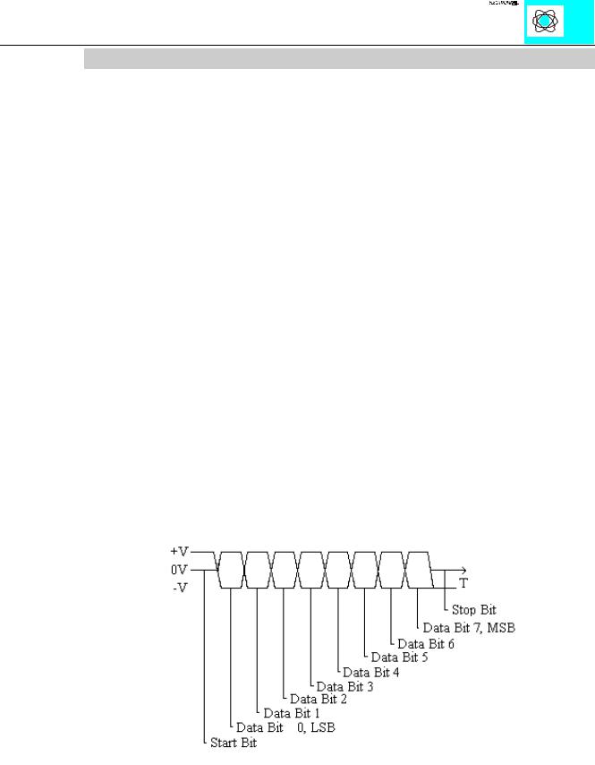
FUNCTION The data transmission takes place at 9.600 baud (default value). 1 startbit, 8 databits and 1 stopbit will be transmitted. No parity is available. The user controls data via the RTS and CTS signals. These signals are generated in the module depending on the loading status of the buffers. These controls can be deactivated by means of an external jumper. RTS and CTS are to be connected.

For testing purposes the Windows 3.11 terminal emulation can be used. A cable with a 9- pole sub-D socket is required. Pin 5 is connected to input M. Pin 2 is connected to TxD and Pin 3 to RxD. RTS and CTS of the module are connected. A hardwarehandshake between terminal emulation and SPS is not possible though.

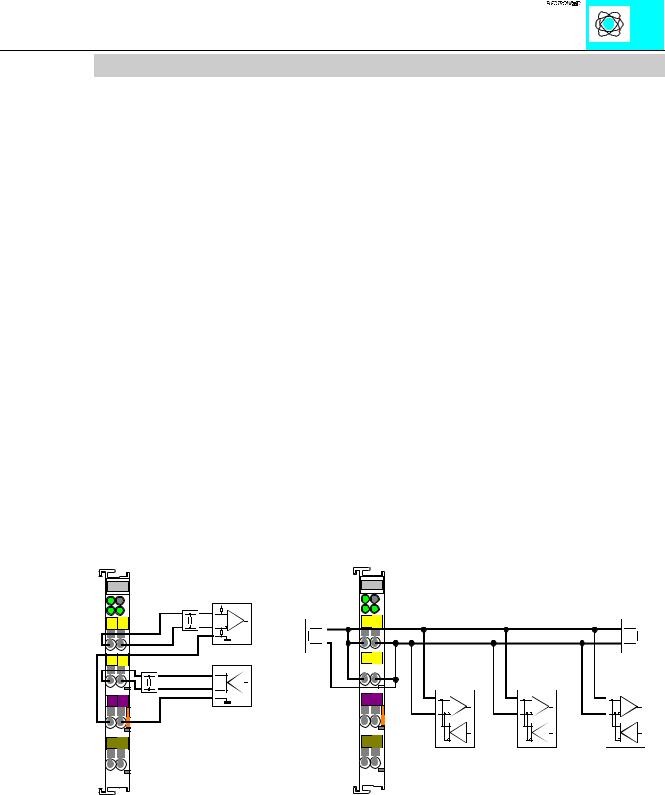
Figure 2: Data Word Signal

RS232,TTY,RS485 750-650,651,653

3

:$*2Ç, 2Ç6<67(0

Description of TTY:

The interface module is designed to operate with all WAGO I/O fieldbus couplers. The TTY interface module allows the connection of TTY-Interface devices to the WAGO I/O SYSTEM. The TTY Interface module can provide gateways within the fieldbus protocol. This allows serial equipment such as printers, barcode readers, and links to local operator interfaces to communicate directly by the fieldbus protocol with the PLC or PC Master.

This module supports no higher level of protocol. Communication is made completely transparent to the fieldbus allowing flexibility in further applications of the serial interface module. The communication protocols are configured at the Master PLC or PC.

The 128 byte input buffer provides for high rates of data transmission. When using lower rates of transmission speed you can collect the received data, with less priority, without loosing data.

The 16 byte output buffer provides for faster transmission of larger data strings.

FUNCTION

The data transmission takes place at 9600 baud (default value). 1 startbit, 8 databits and 1 stopbit will be transmitted. No parity is available. The drivers are high ohmic. The control of data is made by the user software.

The TTY Interface is passive in sending and receiving , thus having no current sources. For data conversion an active partner is needed or an additional current source has to be connected.


UHFHLYHU


FXUUHQW VRXUFH


ZLWK FXUUHQW VRXUFH


P$


P$


TxD TxD

TxD TxD

UHFHLYHU

+

-

+

-


WUDQVPLWWHU ZLWK


FXUUHQW VRXUFH


FXUUHQW VRXUFH


P$


P$


RxD RxD

RxDRxD

WUDQVPLWWHU

+

-

+

-


:$*2

:$*2


TxD TxD

+-

RxDRxD

+-

:$*2

FXUUHQW VRXUFH

P$

UHFHLYHU

WUDQVPLWWHU

SRLQW WR SRLQW FRQQHFWLRQ

SRLQW WR SRLQW FRQQHFWLRQ ZLWK SDVVLYH

EXV FRQQHFWLRQ ZLWK D FXUUHQW VRXUFH

ZLWK DFWLYH SDUWQHUV

SDUWQHUV DQG DGGLWLRQDO FXUUHQW VRXUFHV

DQG D SDVVLYH PRGXOH

RS232,TTY,RS485 750-650,651,653

4

:$*2Ç, 2Ç6<67(0

Description of RS 485:

The interface module is designed to operate with all WAGO I/O fieldbus couplers. The serial interface module allows the connection of RS485 or RS488-Interface devices to the WAGO I/O SYSTEM. The RS485/RS488 Interface module can provide gateways within the fieldbus protocol. This allows serial equipment such as printers, barcode readers, and links to local operator interfaces to communicate directly by the fieldbus protocol with the PLC or PC Master.

This module supports no higher level of protocol. Communication is made completely transparent to the fieldbus allowing flexibility in further applications of the serial interface module. The communication protocols are configured at the Master PLC or PC.

The 128 byte input buffer provides for high rates of data transmission. When using lower rates of transmission speed you can collect the received data, with less priority, without loosing data.

The 16 byte output buffer provides for faster transmission of larger data strings.

FUNCTION The data transmission takes place at 9,600 baud (default value). 1 startbit, 8 databits and 1 stopbit will be transmitted. No parity is available. The drivers are high ohmic. The control of data is made by the user software.

The interface module can be used for bus connections as well as for point to point connections. With bus connections, modules that are not connected to the power supply can also be wired. They do not disturb the bus connection.

TxDTxD

+-

RxDRxD

+-

M M

S S

:$*2

UHFHLYHU

WHUPLQDWLRQ

WUDQVPLWWHU

TxDTxD

WHUPLQDWLRQ


+-

RxDRxD

+-


WUDQVPLWWHU DQG

WUDQVPLWWHU QG

WUDQVPLWWHU DQG


UHFHLYHU

UHFHLYHU

UHFHLYHU

M M

S S

:$*2

SRLQW WR SRLQW FRQQHFWLRQ

EXV FRQQHFWLRQ

RS232,TTY,RS485 750-650,651,653

5

:$*2Ç, 2Ç6<67(0

Structure of input and output data:

The module is a combined analog input and output module with 2 x 16 bit input and output data. The transfer of the data to be transmitted and the received data is made via up to 3 output and 3 input bytes. One control byte and one status byte are used to control the floating data.

Requests are indicated by a change of a bit. An assigned bit indicates execution by adopting the value of the request bit.

Up to 3 characters which have been received via interface can be stored in the input bytes 0 to 2. The output bytes will contain the characters to be sent.

The control byte consists of the following bits:

Control Byte

Bit 7

Bit 6

Bit 5

Bit 4

Bit 3

Bit 2

Bit 1

Bit 0

0

OL2

OL1

OL0

0

IR

RA

TR

Con-

Frames available in output

Constant

Initialization

Reception

Trans-

stant

area, OL2 is always 0.

value must

request

acknow-

mission

value

eg. OL2, OL1, OL0 = 0,1,1

always be 0.


ledgement

request

must

3 characters should be sent


always

and put into the output.


be 0.


The status byte consists of the following bits:

Bit 7

0

Constant value must always be 0.

Status Byte

Bit 6

Bit 5

Bit 4

Bit 3

Bit 2

Bit 1

Bit 0

IL2

IL1

IL0

BUF_F

IA

RR

TA

Frames available in input

Input buffer

Initialization

Reception

Trans-

area, IL2 is always 0. eg.

is full.

acknow-

request

mission

IL2,IL1,IL0 = 0,1,0


ledgement


acknow-

2 characters were received


ledgement

and reside in input 0 and input


1.


RS232,TTY,RS485 750-650,651,653

6

:$*2Ç, 2Ç6<67(0