Материал: m012900e
Fieldbus coupler 750-342 • 37
Starting up ETHERNET TCP/IP fieldbus nodes
Note
The IP address can be allocated under other operating systems (i.e. under Linux) as well as with any other BootP servers.
Attention
The IP address can be allocated in a direct connection via a crossover cable or via a parallel cable and a hub. An allocation over a switch is not possible.
BootP table
Note
Prerequisite for the following steps is the correct installation of the WAGO BootP server.
1.Go to the Start menu, menu item Programs / WAGO Software / WAGO BootP Server and click on WAGO BootP Server configuration.
An editable table will appear: "bootptab.txt".
This table displays the data basis for the BootP server. Directly following the list of all notations used in the BootP table there are two examples for the allocation of an IP address.
"Example of entry with no gateway" and "Example of entry with gateway".
Fig. 3-11: BootP table |
p012908e |
The examples mentioned above contain the following information:
Declaration |
Meaning |
|
node1, |
Any name can be given for the node here. |
|
node2 |
||
|
||
ht=1 |
Specify the hardware type of the network here. |
|
|
The hardware type for ETHERNET is 1. |
|
|
(The numbers are described in RFC1700) |
ha=0030DE000100
ha=0030DE000200
ip= 10.1.254.100 ip= 10.1.254.200
T3=0A.01.FE.01
Specify the hardware address or the MAC-ID of the ETHERNET fieldbus coupler (hexadecimal).
Enter the IP address of the ETHERNET fieldbus coupler (decimal) here.
Specify the gateway IP address here.
Write the address in hexadecimal form.
sm=255.255.0.0 In addition enter the Subnet-mask of the subnet (decimal), where the ETHERNET fieldbus coupler belongs to.
Modular I/O System
ETHERNET TCP/IP

38 • Fieldbus coupler 750-342
Starting up ETHERNET TCP/IP fieldbus nodes
No gateway is required for the local network described in this example. Therefore, the first example: "Example of entry with no gateway" can be used.
2.Move the mouse pointer to the text line: "node1:ht=1:ha=0030DE000100:ip=10.1.254.100" and mark the 12 character hardware address which is entered after ha=...
Enter the MAC-ID of your own network coupler.
3.If you want to give your fieldbus node a name, delete the name "node1" and enter any name in its place.
4.To assign the coupler a desired IP address, mark the IP address specified in the example which is entered after ip=...
Replace it with the IP address you have selected.
5.Because the second example is not necessary at present, insert a “#” in front of the text line of the second example: "# node2:hat=1:ha=003 0DE 0002 00:ip=10.1.254.200:T3=0A.01.FE.01", so that this line will be ignored.
Note
To address more fieldbus nodes, enter a corresponding text line showing the corresponding entries for each node.
6.Save the altered settings in this text file "bootptab.txt". To do this go to the File menu, menu item Save, and close the editor.
BootP Server
7.Now open the dialog window for the WAGO BootP server by going to the Start menu on your screen surface, menu item Program /
WAGO Software / WAGO BootP Server and click on WAGO BootP
Server.
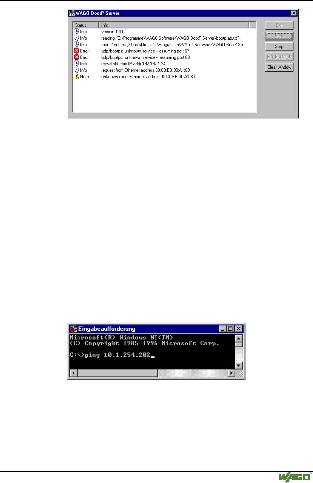
8.Click on the "Start" button in the opened dialog window.
This will activate the inquiry/response mechanism of the BootP protocol. A series of messages will be displayed in the BootP server. The error messages indicate that some services (i.e. port 67, port 68) in the operating system have not been defined.
Modular I/O System
ETHERNET TCP/IP
Fieldbus coupler 750-342 • 39
Starting up ETHERNET TCP/IP fieldbus nodes
Fig. 3-12: Dialog window of the WAGO BootP server with messages |
g012909d |
9.Now it is important to restart the coupler by resetting the hardware . This ensures that the new IP address will be accepted by the coupler.
To do this, cycle power to the fieldbus coupler for approx. 2 seconds.
Following this, the IP address in the coupler is permanently stored and maintained even once the coupler is removed or following a longer voltage failure.
10.Subsequently, click on the "Stop" button and then on the "Exit" button, to close the BootP Server again.
3.1.6.5Testing the function of the fieldbus node
1.To test the communication with the coupler and the correct assignment of the IP address call up the DOS prompt under Start menu / Program / MSDOS Prompt.
2.Enter the command: "ping" with the IP address you have assigned in the following form:
ping [space] XXXX . XXXX . XXXX . XXXX (=IP address). Example: ping 10.1.254.202
Fig. 3-13: Example for the function test of a fieldbus node |
P012910e |
3.When the Return key has been pressed, your PC will receive a response from the coupler, which will then be displayed in the DOS prompt.
If the error message: "Timeout" appears instead, please compare your entries again to the allocated IP address.
4.When the test has been performed successfully, you can close the DOS prompt. The network node has now been prepared for communication.
Modular I/O System
ETHERNET TCP/IP
40 • Fieldbus coupler 750-342
Starting up ETHERNET TCP/IP fieldbus nodes
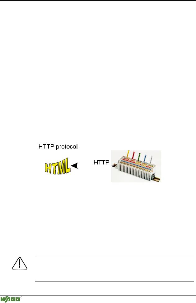
3.1.6.6Reading out the information as HTML pages
The information saved in the fieldbus coupler can be read as an HTML page using a web browser.
•Information on the fieldbus node (Terminal Status):
-Number of digital, analog or complex modules
-Representation of the process image
•Information on the fieldbus coupler (Coupler and Network Details):
-Order number
-Firmware version
-MAC-ID
-IP address
-Gateway address (if applicable)
-Subnet mask
-Number of transmitted and received packets
•Diagnostic information on the fieldbus coupler (Coupler Status):
-Error code
-Error argument
-Error description
|
|
|
|
|
|
|
|
|
|
|
|
Fig. 3-14: Reading out the information via the HTTP protocol |
G012916d |
||||
Please proceed as follows:
1.Open a web browser such as Microsoft Internet-Explorer, Netscape Navigator, ...
2.Simply enter the IP address of your fieldbus node in the address field of the browser and press the Return key.
The first HTML page with the information on your fieldbus coupler will be displayed in the browser window. Use the hyperlinks to find out more information.
Attention
If the pages are not displayed after local access to the fieldbus node, then define in your web browser that, as an exception, no proxyserver is to be used for the IP address of the node.
Modular I/O System
ETHERNET TCP/IP
Fieldbus coupler 750-342 • 41
LED Display
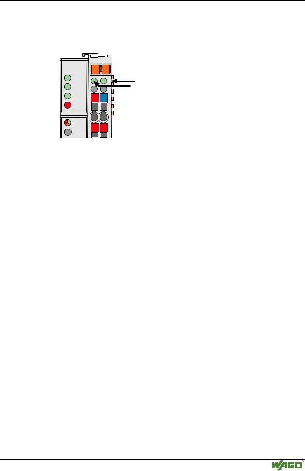
3.1.7LED Display
The coupler possesses several LED’s for displaying the coupler operating status and the complete node status.
ETHERNET |
01 |
02 |
status |
|
voltage supply |
|
|||
ON |
A |
|
|
|
|
-power jumper contacts |
|
||
|
|
|
||
|
|
C |
|
|
LINK |
B |
|
-system |
|
|
D |
|
||
TxD/RxD |
24V 0V |
|
|
|
ERROR |
|
|
|
|
I/O |
+ |
+ |
|
|
|
|
|
||
Fig. 3-15: Display elements 750-342 |
G012901e |
|||
A differentiation is made between the two groups of LEDs.
The first group = fieldbus contains the solid color LEDs having the designation ON (green), LINK (green), TxD/RxD (green) and ERROR (red) indicating the operating status of the communication via ETHERNET.
The second group = internal bus consists of the three-color I/O LED (red/green/orange). This LED is used to display the status of the internal bus and i. e. the status of the fieldbus node.
LEDs located on the right-hand side in the coupler feed section, show the status of the supply voltage.
3.1.7.1Blink code
A blink code displays detailed fault messages. A fault is cyclically displayed using up to 3 different blink sequences.
•The first blink sequence (approx. 10 Hz) indicates the fault display.
•After a pause a second blink sequence appears (approx. 1 Hz). The number of blink impulses gives the fault code.
•The third blink sequence (approx. 1 Hz) appears following a further pause. The number of blink pulses indicates the fault argument.
Modular I/O System
ETHERNET TCP/IP