Материал: m012900e
Fieldbus coupler /controller • 47
Fieldbus controller 750-842
3.2 Fieldbus controller 750-842 |
|
|
This chapter includes: |
|
|
3.2.1 |
Description ..................................................................................... |
48 |
3.2.2 |
Hardware ........................................................................................ |
49 |
1.1.1.1 |
View......................................................................................... |
49 |
1.1.1.2 |
Device supply .......................................................................... |
50 |
1.1.1.3 |
Fieldbus connection ................................................................. |
51 |
1.1.1.4 |
Display elements...................................................................... |
51 |
1.1.1.5 |
Configuration and programming interface............................... |
52 |
1.1.1.6 |
Operating mode switch ............................................................ |
52 |
1.1.1.7 |
Hardware address (MAC-ID) .................................................. |
53 |
3.2.3 |
Operating system ............................................................................ |
54 |
1.1.1.8 |
Start-up .................................................................................... |
54 |
1.1.1.9 |
PLC cycle................................................................................. |
54 |
3.2.4 |
Process image ................................................................................. |
56 |
1.1.1.10 |
Example of a process input image ........................................... |
57 |
1.1.1.11 |
Example of a process output image ......................................... |
58 |
1.1.1.12 |
Process data architecture for MODBUS/TCP ......................... |
59 |
3.2.5 |
Data exchange................................................................................. |
65 |
1.1.1.13 |
Memory areas .......................................................................... |
66 |
1.1.1.14 |
Addressing ............................................................................... |
67 |
1.1.1.15 |
Data exchange between master and I/O modules .................... |
70 |
1.1.1.16 |
Data exchange between PLC functionality (CPU) and I/O |
|
|
modules.................................................................................... |
71 |
1.1.1.1Data exchange between master and PLC functionality (CPU) 72
1.1.1.17Common access of MODBUS master and PLC functionality to
|
outputs ..................................................................................... |
73 |
3.2.6 |
Starting up ETHERNET TCP/IP fieldbus nodes............................ |
75 |
1.1.1.18 |
Note the MAC-ID and establish the fieldbus node.................. |
75 |
1.1.1.19 |
Connecting PC and fieldbus node............................................ |
75 |
1.1.1.20 |
Determining IP addresses ........................................................ |
76 |
1.1.1.21 |
Allocating the IP address to the fieldbus node ........................ |
76 |
1.1.1.22 |
Testing the function of the fieldbus node ................................ |
79 |
1.1.1.23 |
Viewing the HTML pages ....................................................... |
80 |
3.2.7 |
Programming the PFC with WAGO-I/O-PRO 32 .......................... |
82 |
1.1.1.24 |
WAGO-I/O-PRO 32 library elements for ETHERNET .......... |
82 |
1.1.1.25 |
IEC 61131-3-Program transfer ................................................ |
84 |
3.2.8 |
LED Display ................................................................................... |
87 |
1.1.1.26 |
Blink code................................................................................ |
87 |
1.1.1.27 |
Fieldbus status ......................................................................... |
88 |
1.1.1.28 |
Node status............................................................................... |
88 |
1.1.1.29 |
Fault message via blink code from the I/O-LED ..................... |
90 |
1.1.1.30 |
Supply voltage status ............................................................... |
91 |
3.2.9 |
Fault behavior ................................................................................. |
92 |
1.1.1.31 |
Fieldbus failure ........................................................................ |
92 |
1.1.1.32 |
Internal bus fault ...................................................................... |
92 |
3.2.10 |
Technical Data................................................................................ |
93 |
Modular I/O System
ETHERNET TCP/IP

48 • Fieldbus controller 750-842 Description
3.2.1Description
The programmable fieldbus controller 750-842 (short: PFC) combines the ETHERNET TCP/IP -functions of the fieldbus coupler 750-with that of a programmable logic control (PLC).
The application program is created with WAGO-I/O-PRO 32 in accordance with IEC 61131-3.
All input signals of the sensors are grouped in the controller. According to the IEC 61131-3 programming, process data treatment occurs locally in the PFC. The link results created in this manner can be put out directly to the actuators or transmitted to the higher ranking control system via the bus.
To be able to transmit process data via ETHERNET, the controller supports a number of network protocols. The process data exchange is made with the aid of the MODBUS/TCP protocol.
The programmer has the option to use function modules for programming clients and servers for all transport protocols (TCP, UDP, etc.) via a socket-API. He has access to all fieldbus and I/O data.
Once the ETHERNET TCP/IP fieldbus controller is connected, it detects all I/O modules connected to the node and produces a local process image on the basis of the detected modules. This can be a mixed arrangement of analog (word-by-word data exchange) and digital (bit-by-bit data exchange) modules. The local process image is subdivided into an input and an output data area.
The data of the analog modules is mapped into the process image in the order of their position after the bus coupler.
The bits of the digital modules are grouped to form words and also mapped into the process image once mapping of the analog modules is completed. Once the number of digital I/O’s exceeds 16 bits, the coupler automatically starts another word.
Information on configuration, status and the I/O data of the fieldbus node are stored in the fieldbus controller as HTML pages. These pages can be read via a conventional WEB browser.
Modular I/O System
ETHERNET TCP/IP
Fieldbus controller 750-842 • 49
Hardware
3.2.2Hardware
3.2.2.1View
|
ETHERNET |
01 |
02 |
status |
|
|
voltage supply |
||||
|
ON |
A |
|
||
|
|
-power jumper contacts |
|||
|
|
C |
|||
fieldbus |
|
|
|||
LINK |
B |
D |
-system |
||
connection |
|
||||
|
|
data contacts |
|||
TxD/RxD |
|
|
|||
RJ 45 |
24V 0V |
||||
|
|||||
|
ERROR |
|
|
supply |
|
|
|
|
|
24V |
|
|
I/O |
|
|
0V |
|
|
+ |
+ |
|
||
|
USR |
supply via |
|||
|
|
|
|||
|
|
|
|
power jumper contacts |
|
|
|
|
|
24V |
|
|
|
- |
- |
|
|
|
50-842 |
|
|
0V |
|
|
7 |
|
|
||
|
|
|
|
||
flap open
|
power jumper contacts |
|
configuration and |
mode switch |
|
programming interface |
||
|
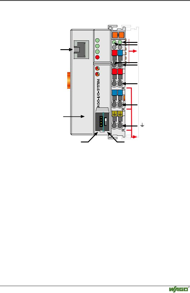
Fig. 3-17: Fieldbus controller ETHERNET TCP/IP |
g084200e |
The fieldbus controller comprises of:
•Device supply with internal system supply module for the system supply as well as power jumper contacts for the field supply via assembled I/O modules
•Fieldbus interface with the bus connection
•Display elements (LED’s) for status display of the operation, the bus communication, the operating voltages as well as for fault messages and diagnosis
•Configuration and programming interface
•Operating mode switch
•Electronics for communication with the I/O modules (internal bus) and the fieldbus interface
Modular I/O System
ETHERNET TCP/IP
50 • Fieldbus controller 750-842 Hardware
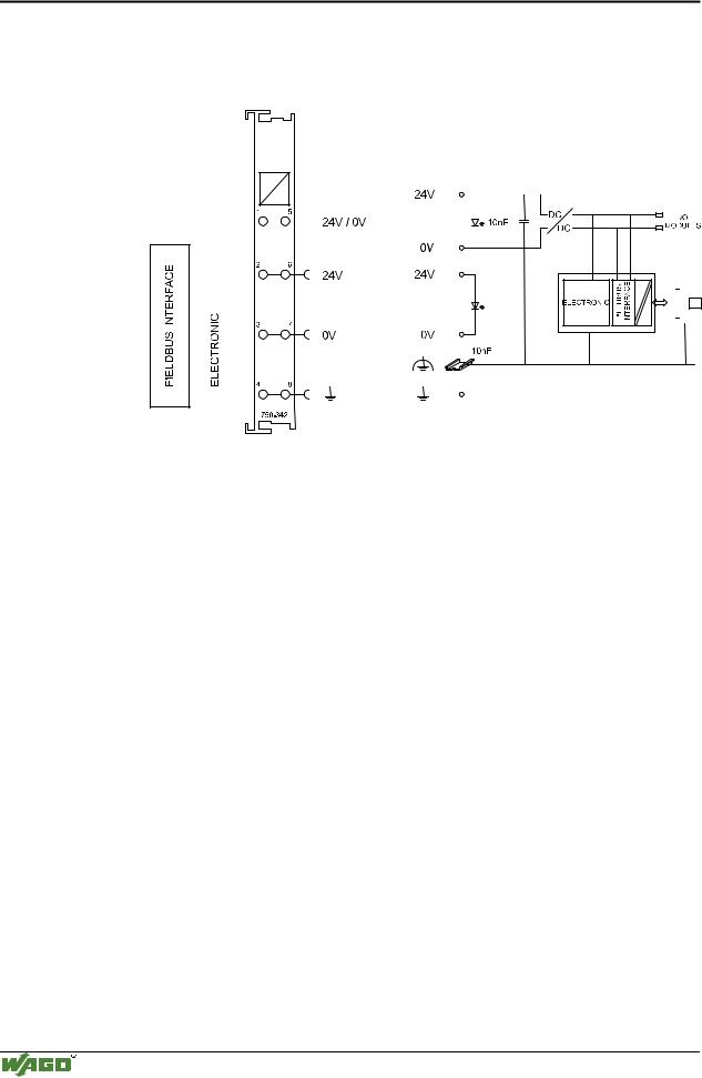
3.2.2.2Device supply
The supply is via fed in via terminal blocks with CAGE CLAMP® connection. Device supply is intended for system supply and field side supply.
|
|
|
|
|
|
|
|
|
|
|
|
|
|
|
|
|
|
|
|
|
|
|
|
|
|
|
|
|
|
|
|
|
|
|
|
|
|
|
|
|
|
|
|
|
|
|
|
|
|
|
|
|
|
|
|
|
|
|
|
|
|
|
|
|
|
|
|
|
|
|
|
|
|
|
|
|
|
|
|
|
|
|
|
|
|
|
|
|
|
|
|
|
|
|
|
|
|
|
|
|
|
|
|
|
|
|
|
|
|
|
|
|
|
|
|
|
|
|
|
|
|
|
|
|
|
|
|
|
|
|
|
|
|
|
|
|
|
|
|
|
|
|
|
|
|
|
|
|
|
|
|
|
|
|
|
|
|
|
|
|
|
|
|
|
|
|
|
|
|
|
|
|
|
|
|
|
|
|
|
|
|
|
|
|
|
|
|
|
|
|
|
|
|
|
|
|
|
|
|
|
|
|
|
|
|
|
|
|
|
|
|
|
|
|
|
|
|
|
|
|
|
|
|
|
|
|
|
|
|
|
|
|
|
|
|
|
|
|
|
|
|
|
|
|
|
|
|
|
|
|
|
|
|
|
|
|
|
|
|
|
|
|
|
|
|
|
|
|
|
|
|
|
|
|
|
|
|
|
|
|
|
|
|
|
|
|
|
|
|
|
|
|
|
|
|
|
|
|
|
|
|
|
|
|
|
|
|
|
|
|
|
|
|
|
|
|
|
|
|
|
|
|
|
|
|
|
|
|
|
|
|
|
|
|
|
|
|
|
|
|
|
|
|
|
|
|
|
|
|
|
|
|
|
|
|
|
|
|
|
|
|
|
|
|
|
|
|
|
|
|
|
|
|
|
|
|
|
|
|
|
|
|
|
|
|
|
|
|
|
|
|
|
|
|
|
|
|
|
|
|
|
|
|
|
|
|
|
|
|
|
|
|
|
|
|
|
|
|
|
|
|
|
|
|
|
|
|
|
|
|
|
|
|
|
|
|
|
|
|
|
|
|
|
|
|
|
|
|
|
|
|
|
|
|
|
|
|
|
|
|
|
|
|
|
|
|
|
|
|
|
|
|
|
|
|
|
|
|
|
|
|
|
|
|
|
|
|
|
|
|
|
|
|
|
|
|
|
|
|
|
|
|
|
|
|
|
|
|
|
|
|
|
|
|
|
|
|
|
|
|
|
|
|
|
|
|
|
|
|
|
|
|
|
|
|
|
|
|
|
|
|
|
|
|
|
|
|
|
|
|
|
|
|
|
|
|
|
|
|
|
|
|
|
|
|
|
|
|
|
|
|
|
|
|
|
|
|
|
|
|
|
|
|
|
|
|
|
|
|
|
|
|
|
|
|
|
|
|
|
|
|
|
|
|
|
|
|
|
|
|
|
|
|
|
|
|
|
|
|
|
|
|
|
|
|
|
|
|
|
|
|
|
|
|
|
|
|
|
|
Fig. 3-18: Device supply |
|
|
|
|
|
|
|
|
|
|
|
|
|
G034201e |
|||||||||||||||||
The integrated internal system supply module generates the necessary voltage to supply the electronics and the connected I/O modules.
The fieldbus interface is supplied with electrically isolated voltage from the internal system supply module.
Modular I/O System
ETHERNET TCP/IP
Fieldbus controller 750-842 • 51
Hardware
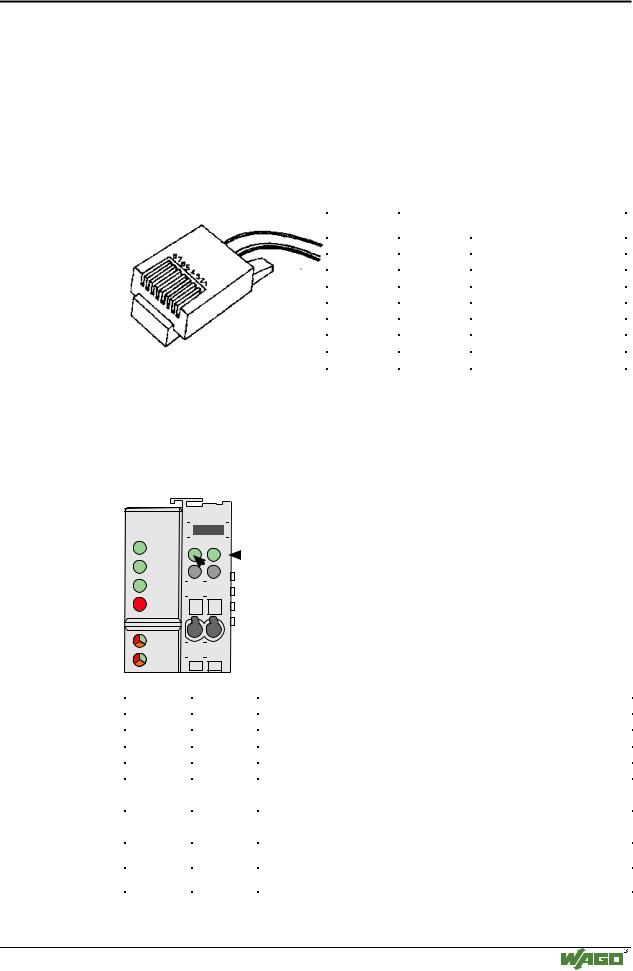
3.2.2.3Fieldbus connection
Connection to the fieldbus is by a RJ45 connector. A category 5, shielded/unshielded twisted pair cable (S-UTP) with an impedance of 100 Ohm ± 15% is mandatory as a connecting line for the 10BaseT Interface. The connection point is physically lowered for the coupler/controller to fit in an 80 mm high switch box once connected.
The electrical isolation between the fieldbus system and the electronics is achieved by means of DC/DC converters and optocouplers in the fieldbus interface.
Contact |
Signal |
|
1 |
TD + |
Transmit + |
2 |
TD - |
Transmit - |
3 |
RD + |
Receive + |
4 |
|
free |
5 |
|
free |
6 |
RD - |
Receive - |
7 |
|
free |
8 |
|
free |
Fig. 3-19: RJ45-connector and RJ45 connector configuration
3.2.2.4Display elements
The operating condition of the fieldbus controller or node is displayed via light diodes (LED).
|
|
|
|
|
|
|
|
|
|
|
|
status |
|
|
ETHERNET |
|
01 |
|
02 |
|
|
|
|
|
|
|
|
|
|
|
|
|
|
|
|
||||||
|
|
|
|
|
|
|
|
|
|
|
|
voltage supply |
|
|
ON |
A |
|
|
|
|
|
|
|
|
-power jumper contacts |
|
|
|
|
B |
|
|
C |
|
|
|
|
|
|
||
|
|
|
|
|
|
|
|
|
|
||||
|
LINK |
|
|
|
|
D |
|
|
|
|
|
-system |
|
|
TxD/RxD |
|
24V |
0V |
|
|
|
|
|
|
|
|
|
|
|
|
|
|
|||||||||
|
ERROR |
|
|
|
|
|
|
|
|
|
|
|
|
|
|
|
|
|
|
|
|
|
|
|
|
|
|
|
I/O |
|
|
|
|
|
|
|
|
|
|
|
|
|
|
|
|
|
|
|
|
|
|
|
|
|
|
|
|
|
|
|
|
|
|
|
|
|
|
|
|
|
|
|
|
|
|
|
|
|
|
|
|
|
|
|
|
|
|
|
|
|
|
|
|
|
|
|
|
|
+ |
+ |
|
|
|
|
|
|
|
|
|||
|
USR |
|
|
|
|
|
|
|
|
|
|||
|
|
|
|
|
|
|
|
|
|
|
|
|
|
Fig. 3-20: Display elements 750-842 |
G012902e |
||||||||||||
|
|
|
|
|
|
||||||||
|
LED |
|
Color |
Meaning |
|
||||||||
|
ON |
|
green |
Fieldbus initialization is correct |
|
||||||||
|
LINK |
|
green |
Link to a physical network exists |
|
||||||||
|
TxD/RxD |
|
green |
Data exchange taking place |
|
||||||||
|
ERROR |
|
red |
Error on the fieldbus |
|
||||||||
|
IO |
|
red /green |
The ’I/O’-LED indicates the operation of the node and signals faults |
|||||||||
|
|
|
/ orange |
encountered |
|
||||||||
|
USR |
|
red /green |
The ’USR’ LED can be selected by a user program in a programma- |
|||||||||
|
|
|
/ orange |
ble fieldbus controller |
|
||||||||
|
A |
|
green |
Status of the operating voltage – system |
|
||||||||
|
|
|
|
|
|
||||||||
|
C |
|
green |
Status of the operating voltage – power jumper contacts |
|
||||||||
|
|
|
|
|
|
|
|
|
|
|
|
|
|
Modular I/O System
ETHERNET TCP/IP