Материал: m012900e
Fieldbus controller 750-842 • 57
Example of process input image
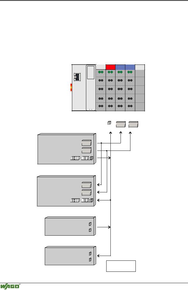
3.2.4.1Example of a process input image
The following figure is an example of a process input image. The configuration comprises of 16 digital and 8 analog inputs.
The process image thus has a data length of 8 words for the analog and 1 word for the digital inputs, i.e. 9 words in total.
Ethernet
 ON
ON
 LINK
LINK
 TxD/RxD
 ERROR
ERROR
 I/O
I/O
SY STEM |
|
W AGO I/O |
750-842 |
DI DI AI AI DI AI DI AI
Input modules 750402 402 472 472
Bit 1 1
Process input image |
|
|
Word1 Word1 |
|
Bit 4 |
4 |
Word2 Word2 |
||
(Word) |
||||
|
|
|
402 476
|
1 |
|
Word1 |
4 |
Word2 |
402 476
|
1 |
|
Word1 |
4 |
Word2 |
addresses |
|
|
|
|
MODBUS PFC |
|
|
||
0x0000 %IW0 |
Word1 |
|
||
0x0001 %IW1 |
Word2 |
|
||
0x0002 %IW2 |
Word1 |
|
||
0x0003 %IW3 |
Word2 |
|
||
0x0004 %IW4 |
Word1 |
|
||
0x0005 %IW5 |
Word2 |
|
||
0x0006 %IW6 |
Word1 |
|
||
0x0007 %IW7 |
Word2 |
|
||
0x0008 %IW8 |
|
|
|
|
Highbyte |
Lowbyte |
|
||
Process input image |
|
|||
|
(Bit) |
|
||
addresses |
|
|||
MODBUS PFC |
|
|||
0x0000 |
%IX8.0 |
|
||
0x0001 |
%IX8.1 |
|
||
0x0002 |
%IX8.2 |
|
||
0x0003 |
%IX8.3 |
|
||
0x0004 |
%IX8.4 |
|
||
0x0005 |
%IX8.5 |
|
||
0x0006 |
%IX8.6 |
|
||
0x0007 |
%IX8.7 |
|
||
0x0008 |
%IX8.8 |
|
||
0x0009 |
%IX8.9 |
DI: Digital Input |
||
0x000A %IX8.10 |
||||
AI:Analog Input |
||||
0x000B %IX8.11 |
||||
|
||||
0x000C %IX8.12 0x000D %IX8.13 0x000E %IX8.14 0x000F %IX8.15
Fig. 3-24: Example of a process input image |
G012924e |
Modular I/O System
ETHERNET TCP/IP
58 • Fieldbus controller 750-842
Example of process output image
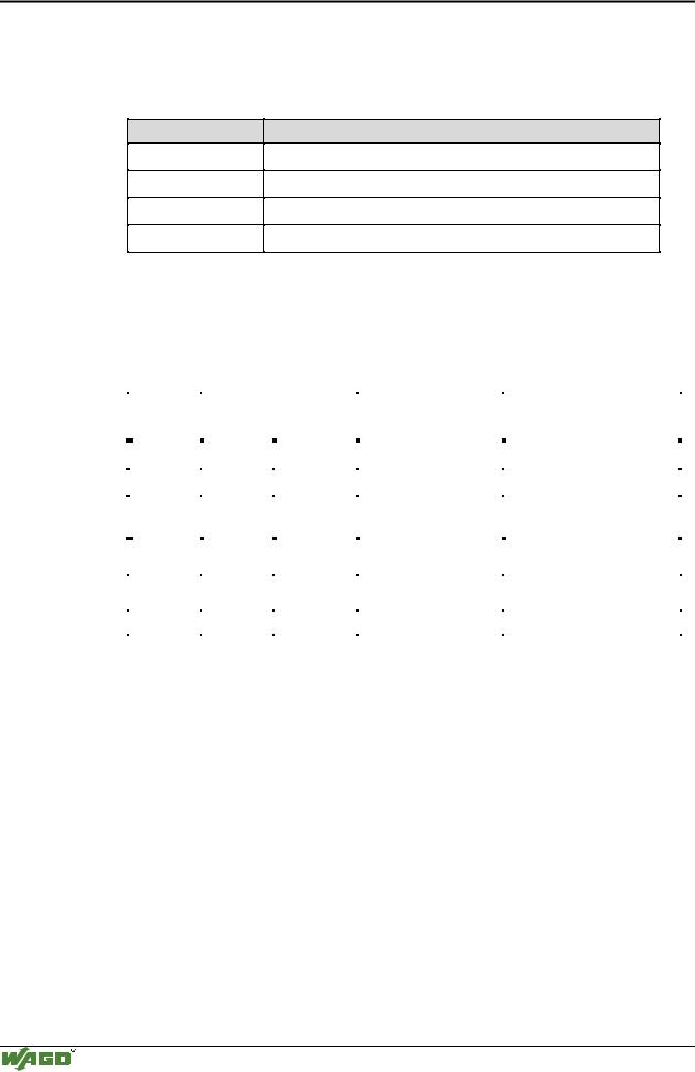
3.2.4.2Example of a process output image
The following example for the process output image comprises of 2 digital and 4 analog outputs.
It comprises of 4 words for the analog and 1 word for the digital outputs, , i.e. 5 words in total.
In addition, output data can be read back with an offset of 200hex (0x0200) added to the MODBUS address.
Ethernet
 ON
ON
 LINK
LINK
 TxD/RxD
 ERROR
ERROR
SY STE M |
|
W AGO I /O |
750-842 |
|
|
|
|
|
|
DO AO AO
Output modules |
750 - 501 |
550 |
550 |
|
|
|
Bit 1 |
|
|
|
|
|
Word1 |
Word1 |
Process output image |
Bit 2 |
Word2 |
Word2 |
|
|
|
|
||
(Word) |
|
|
|
|
MODBUS addresses |
|
|
|
|
0x0000 / 0x0200 %QW0 |
Word1 |
|
|
|
0x0001 / 0x0201 %QW1 |
Word2 |
|
|
|
0x0002 / 0x0202 %QW2 |
Word1 |
|
|
|
0x0003 / 0x0203 %QW3 |
|
|
|
|
Word2 |
|
|
|
|
|
|
|
|
|
0x0004 / 0x0204 %QW4 |
|
|
|
|
Highbyte |
Lowbyte |
|
|
|
Process input image |
|
|
|
|
(Word) |
|
|
|
|
MODBUS addresses |
|
|
|
|
0x0200 %QW0 |
Word1 |
|
|
|
Word2 |
|
|
|
|
0x0201 %QW1 |
|
|
|
|
|
|
|
|
|
0x0202 %QW2 |
Word1 |
|
|
|
0x0203 %QW3 |
Word2 |
|
|
|
0x0204 %QW4 |
|
|
|
|
Highbyte |
Lowbyte |
|
|
|
Process output image |
|
|
|
|
(Bit) |
|
|
|
|
MODBUS addresses |
|
|
|
|
0x0000 / 0x0200 %QX4.0 |
|
|
|
|
0x0001 / 0x0201 %QX4.1 |
|
|
|
|
Process input image |
|
|
|
|
(Bit) |
|
|
|
|
MODBUS addresses |
|
|
|
|
0x0200 %QX4.0 |
|
|
|
|
0x0201 %QX4.1 |
|
|
|
|
DO: Digital Output
AO: Analog Output
Fig. 3-25: Example of a process output image |
G012925e |
Modular I/O System
ETHERNET TCP/IP

Fieldbus controller 750-842 • 59
Process data architecture for MODBUS/TCP
3.2.4.3Process data architecture for MODBUS/TCP
For some bus modules or their variations, the process data architecture is specific for the fieldbus controller used.
In the case of the ETHERNET controller with MODBUS/TCP the control/status byte is always masked in addition to the data bytes. This is required for the two-directional data exchange of the bus module with the higherranking control system. The control byte is transmitted from the control system to the module and the status byte from the module to the control system. This allows, for example, the display of overshooting or undershooting of the area.
Attention
Please refer to the respective bus module description in Chapter 4 "I/O modules" for the specific architecture of the respective control/status byte.
The following shows the representation of some selected modules in the process image.
In the examples, the order in which the modules are physically arranged in the node reflects the order in the image table starting with register address 0x0000. If the module is located at any other position in the fieldbus node, the process data of all previous byte-wise oriented modules have to be taken into account. In the process image, this results in a basic register address for the module. To address its process data words, the quoted offset is added to this basic address.
If an analog input or output module is added, it takes up 2 x 16 Bit input or output data.
With the ETHERNET fieldbus controller with MODBUS/TCP the process image is organized word-by-word (word-alignment) and the control/status byte is always a low byte.
Modular I/O System
ETHERNET TCP/IP
60 • Fieldbus controller 750-842
Process data architecture for MODBUS/TCP
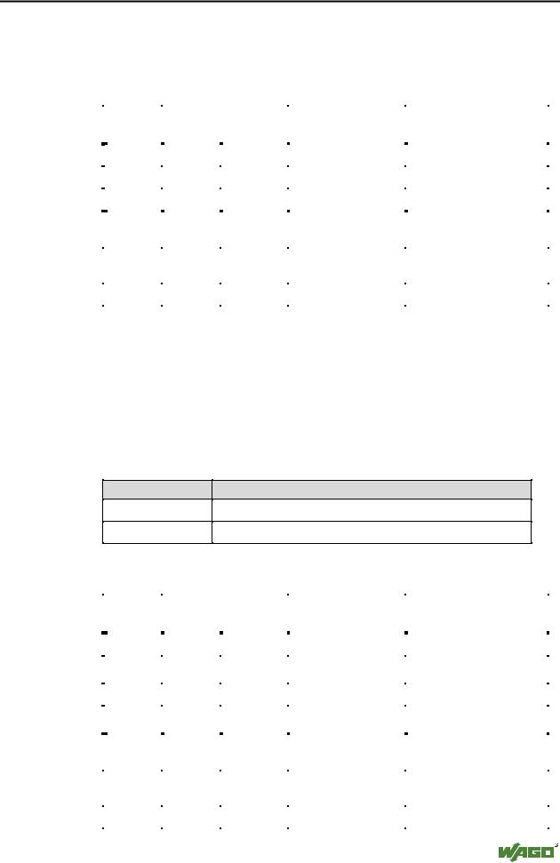
3.2.4.3.1 750-404, /000-00X Counter modules
This process data architecture holds true for the counter modules 750-404, 750-404/000-001, 750-404/000-002 and 750–404/000-004.
Item number:
750-404
750-404/000-001
750-404/000-002
750-404/000-004
Description:
Up/Down Counter
2 Channel Up Counter with enable input
Peak Time Counter
Up/Down Counter (switching outputs)
The data format of the counter modules five bytes is mapped out by the module as four data bytes and one additional control/status byte. The module supplies a 32 bit counter-output, while occupying 3 words each in the process image with word-alignment.
|
Address |
Bytes |
|
|
|
Comment |
|
Module |
|
Offset |
High |
|
Low |
|
|
|
|
|
|
|
|
|
|
|||
|
|
|
|
|
|
|
|
|
|
0 |
|
|
C/S |
|
Control-/ Status byte |
|
Module 1: |
|
|
|
|
|
|
|
750-404, |
|
|
1 |
D1 |
|
D0 |
|
|
||
|
|
|
|
750-404/000-001, |
||||
|
|
|
|
|
|
Data bytes |
||
|
2 |
D3 |
|
D2 |
|
750-404/000-002, |
||
|
|
|
|
|
|
|
750-404/000-004 |
|
|
3 |
User data |
|
User data |
|
Data bytes |
|
Module 2: |
|
|
|
|
Analog module Channel 1 |
||||
|
|
|
|
|
|
|
|
|
|
4 |
User data |
|
User data |
|
Data bytes |
|
Module 2: |
|
|
|
|
Analog module Channel 2 |
||||
|
|
|
|
|
|
|
|
|
|
... |
... |
... |
... |
... |
|||
The input bytes D0 to D3 form the 32 bit counter-output.
In the output bytes D0 to D3 the initial value of the counter can be set.
Modular I/O System
ETHERNET TCP/IP
Fieldbus controller 750-842 • 61
Process data architecture for MODBUS/TCP
3.2.4.3.2 750-404/000-005 2 Channel Up Counter 16 Bit
The data format of the counter modules five bytes is mapped out by the module as four data bytes and one additional control/status byte, while occupying 3 words each with word-alignment.
|
Address |
Bytes |
|
|
|
Comment |
|
Module |
|
Offset |
High |
|
Low |
|
|
|
|
|
|
|
|
|
|
|||
|
|
|
|
|
|
|
|
|
|
0 |
|
|
C/S |
|
Control/ Statusbyte |
|
|
|
|
|
|
|
|
|
|
Module 1: |
|
1 |
D1 |
|
D0 |
|
Data bytes Counter 1 |
|
|
|
|
|
750-404/000-005 |
|||||
|
|
|
|
|
|
|
||
|
2 |
D3 |
|
D2 |
|
Data bytes Counter 2 |
|
|
|
|
|
|
|
|
|
|
|
|
3 |
User data |
|
User data |
|
Data bytes |
|
Module 2: |
|
|
|
|
Analog module Channel 1 |
||||
|
|
|
|
|
|
|
|
|
|
|
|
|
|
|
|
|
|
|
4 |
User data |
|
User data |
|
Data bytes |
|
Module 2: |
|
|
|
|
Analog module Channel 2 |
||||
|
|
|
|
|
|
|
|
|
|
|
|
|
|
|
|||
|
... |
... |
... |
... |
... |
|||
|
|
|
|
|
|
|
|
|
The input bytes D0 and D1 form the 16 bit reading of counter 1 and the input bytes D2 and D3 form the 16 bit reading of counter 2.
When setting the counter, the load value of counter 1 is transferred in the output bytes D0 and D1. The load value of counter 2 is transferred respectively in the output bytes D2 and D3.
3.2.4.3.3 750-511, /000-002 2-Channel Digital Pulsewidth module
This process data architecture holds true for the 2 Channel Pulsewidth modules 750-511 and 750–511/000-002.
Item-No.: Description:
750-511
750-511/000-002
2DO 24V DC 0.1A Pulsewidth
2DO 24V DC 0,1A Pulsewidth 100Hz
The process image of the 750-511 and 750-511/000-002 appears with 6 bytes of input and 6 bytes of output data, while occupying 4 words each in the process image with word-alignment.
|
|
Address |
Bytes |
|
|
|
Comment |
|
Module |
|
|
|
Offset |
High |
|
Low |
|
|
|
|
|
|
|
|
|
|
|
|
|
|||
|
|
|
|
|
|
|
|
|
|
|
|
|
0 |
|
|
C/S-0 |
|
Control / Status byte |
|
Module 1 Channel 1: |
|
|
|
|
|
|
|
|
|
750-511, |
|
|
|
|
1 |
D1-0 |
|
D0-0 |
|
Data bytes |
|
||
|
|
|
|
750-511/000-002 |
|
|||||
|
|
2 |
|
|
C/S-1 |
|
Control / Status byte |
|
Module 1 Channel 2: |
|
|
|
|
|
|
|
|
|
750-511, |
|
|
|
|
3 |
D1-1 |
|
D0-1 |
|
Data bytes |
|
||
|
|
|
|
750-511/000-002 |
|
|||||
|
|
|
|
|
|
|
|
|
||
|
|
4 |
User data |
|
User data |
|
Data bytes |
|
Module 2: |
|
|
|
|
|
|
Analog Module Channel 1 |
|
||||
|
|
|
|
|
|
|
|
|
|
|
|
|
|
|
|
|
|
|
|
|
|
|
|
5 |
User data |
|
User data |
|
Data bytes |
|
Module 2: |
|
|
|
|
|
|
Analog Module Channel 2 |
|
||||
|
|
|
|
|
|
|
|
|
|
|
|
|
|
|
|
|
|
|
|||
|
|
... |
... |
... |
... |
... |
|
|||
|
|
|
|
|
|
|
|
|
|
|
|
|
|
|
|
|
|
|
|
|
|
Modular I/O System
ETHERNET TCP/IP