Материал: m012900e
62 • Fieldbus controller 750-842
Process data architecture for MODBUS/TCP
3.2.4.3.4 750-630, /000-00X SSI encoder interface 24 Bit
This process data architecture holds true for the SSI encoder interface modules 750-630, 750-630/000-001 and 750–630/000-006.
Item-No.:
750-630
750-630/000-001
750-630/000-006
Description:
SSI encoder interface 24Bit, 125kHz Gray code, alternative Data format
SSI encoder interface 24Bit, 125kHz Binary code, alternative Data format
SSI encoder interface 24Bit, 250kHz Gray code, alternative Data format
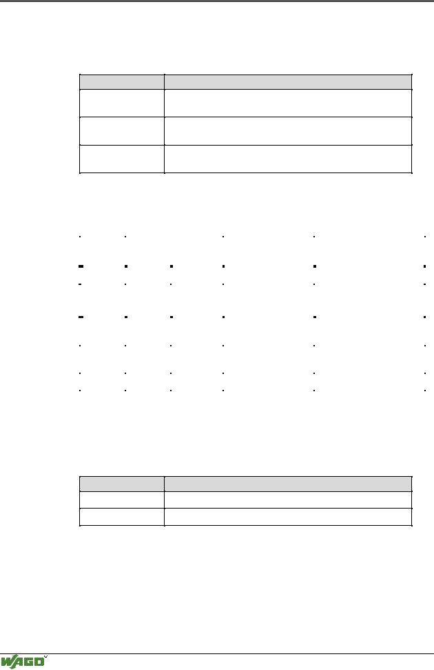
The module is seen like an analog input with 2 x 16 Bit input data, i.e. with a total of 4 bytes user data. Here 2 words in the input area of the local process image are occupied with word-alignment.
|
Address |
|
Bytes |
|
|
|
Comment |
|
Module |
|
Offset |
|
High |
|
Low |
|
|
|
|
|
|
|
|
|
|
|
|||
|
|
|
|
|
|
|
|
|
|
|
0 |
|
D1 |
|
D0 |
|
|
|
Module 1: |
|
|
|
|
|
|
|
Data bytes |
750-630, |
|
|
1 |
|
D3 |
|
D2 |
|
|||
|
|
|
|
750-630/000-001, |
|||||
|
|
|
|
|
|
|
|
||
|
|
|
|
|
|
|
|
750-630/000-006 |
|
|
2 |
|
User data |
|
User data |
|
Data bytes |
|
Module 2: |
|
|
|
|
|
Analog module Channel 1 |
||||
|
|
|
|
|
|
|
|
|
|
|
|
|
|
|
|
|
|
|
|
|
3 |
|
User data |
|
User data |
|
Data bytes |
|
Module 2: |
|
|
|
|
|
Analog module Channel 2 |
||||
|
|
|
|
|
|
|
|
|
|
|
|
|
|
|
|
||||
|
... |
... |
... |
... |
... |
||||
|
|
|
|
|
|
|
|
|
|
3.2.4.3.5 750-631, /000-001 Incremental Encoder Interface
This process data architecture holds true for the Incremental Encoder Interface modules 750-631 and 750–631/000-001.
Item-No.:
750-631
750-631/000-001
Description:
Incremental encoder interface, 4 times sampling
Incremental encoder interface, 1 times sampling
The bus module 750-631 and 750-631/000-001 002 appears with 6 bytes of input and 6 bytes of output data and occupies 4 words each with word-align- ment.
Modular I/O System
ETHERNET TCP/IP

Fieldbus controller 750-842 • 63
Process data architecture for MODBUS/TCP
|
Address |
Bytes |
|
|
|
Comment |
|
Module |
|
|
Offset |
High |
|
Low |
|
|
|
|
|
|
|
|
|
|
|
|
|||
|
|
|
|
|
|
|
|
|
|
|
0 |
|
|
C/S |
|
Control / Status byte |
|
|
|
|
|
|
|
|
|
|
|
Module 1: |
|
|
1 |
D1 |
|
D0 |
|
ead/set counter word |
|
|
|
|
|
|
|
|
|||||
|
|
|
|
|
|
|
750-631, |
|
|
|
3 |
|
|
(D2)*) |
|
(period) |
|
||
|
|
|
|
750-631/000-001 |
|
||||
|
4 |
D4 |
|
D3 |
|
read latch word |
|
|
|
|
|
|
|
|
|
|
|
|
|
|
5 |
User data |
|
User data |
|
Data bytes |
|
Module 2: |
|
|
|
|
|
Analog module Channel 1 |
|
||||
|
|
|
|
|
|
|
|
|
|
|
|
|
|
|
|
|
|
|
|
|
6 |
User data |
|
User data |
|
Data bytes |
|
Module 2: |
|
|
|
|
|
Analog module Channel 2 |
|
||||
|
|
|
|
|
|
|
|
|
|
|
|
|
|
|
|
|
|||
|
... |
... |
... |
... |
... |
|
|||
|
|
|
|
|
|
|
|
|
|
The control / status byte is in the low byte on offset 0.
The data word D0/D1 contains the counter word (read/set), whereas the data word D3/D4 contains the latch word (read).
*) In the operating mode of permanent period measurement, the period duration is in D2 together with D3/D4.
3.2.4.3.6750-650 RS232 Interface module,
750-651 TTY-,20 mA Current Loop,
750-653 RS485 Interface module
This process data architecture holds true for the modules 750-650, 750-651 and 750–653.
Item-No.: |
Description: |
|
|
750-650 |
RS 232 C Interface 9600,n,8,1 |
|
|
750-651 |
TTY Interface, 20 mA Current Loop |
|
|
750-653 |
RS485 Interface |
|
|
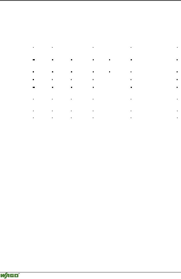
The modules appear on the bus as a combined analog input and output module with 3 x 16-bit input and output data, i.e. with a total of 4 bytes user data. Here 2 words each are occupied with word-alignment.
|
|
Address |
|
Bytes |
|
|
|
Comment |
|
|
|
|
Module |
|
|
|
Offset |
|
High |
|
Low |
|
|
|
|
|
|
|
|
|
|
|
|
|
|
|
|
|
|
|
|
|||
|
|
|
|
|
|
|
|
|
|
|
|
|
|
|
|
|
0 |
|
D0 |
|
C/S |
|
Data |
|
Control / |
|
|
Module 1: |
|
|
|
|
|
|
byte |
|
Status byte |
|
750-650, |
|
||||
|
|
|
|
|
|
|
|
|
|
|
||||
|
|
|
|
|
|
|
|
|
|
|
|
750-651, |
|
|
|
|
1 |
|
D2 |
|
D1 |
|
Data bytes |
|
|
||||
|
|
|
|
|
|
|
||||||||
|
|
|
|
|
|
750-653 |
|
|||||||
|
|
2 |
|
User data |
|
User data |
|
Data bytes |
|
|
Module 2: |
|
||
|
|
|
|
|
|
|
Analog module Channel 1 |
|
||||||
|
|
|
|
|
|
|
|
|
|
|
|
|
|
|
|
|
|
|
|
|
|
|
|
|
|
|
|
|
|
|
|
3 |
|
User data |
|
User data |
|
Data bytes |
|
|
Module 2: |
|
||
|
|
|
|
|
|
|
Analog module Channel 2 |
|
||||||
|
|
|
|
|
|
|
|
|
|
|
|
|
|
|
|
|
|
|
|
|
|
|
|
|
|
||||
|
|
... |
... |
... |
|
|
... |
|
... |
|
||||
|
|
|
|
|
|
|
|
|
|
|
|
|
|
|
|
|
|
|
|
|
|
|
|
|
|
|
|
|
|
Modular I/O System
ETHERNET TCP/IP
64 • Fieldbus controller 750-842
Process data architecture for MODBUS/TCP
3.2.4.3.7 750-650/000-001 RS232 Interface module 5 Byte
The RS232 interface module 750-650 can also be operated with a data format of 5 bytes and one Control/Status byte, i.e. a total of 6 bytes user data. For this data format, order the variation with the part number 750-650/000-001, occupying 3 words each in the input and output area of the process image with word-alignment.
|
Address |
|
Bytes |
|
|
|
Comment |
|
|
|
Module |
|
Offset |
|
High |
|
Low |
|
|
|
|
|
|
|
|
|
|
|
|
|
|
|
|||
|
|
|
|
|
|
|
|
|
|
|
|
|
0 |
|
D0 |
|
C/S |
|
Data |
|
Control / |
|
|
|
|
|
|
byte |
|
Status byte |
|
|
|||
|
|
|
|
|
|
|
|
|
Module 1: |
||
|
|
|
|
|
|
|
|
|
|
|
|
|
|
|
|
|
|
|
|
|
|
|
|
|
1 |
|
D2 |
|
D1 |
|
Data bytes |
750-650/000-001 |
|||
|
|
|
|
|
|
|
|
|
|||
|
2 |
|
D4 |
|
D3 |
|
|
|
|||
|
|
|
|
|
|
||||||
|
|
|
|
|
|
|
|
|
|||
|
|
|
|
|
|
|
|
|
|
|
|
|
3 |
|
User data |
|
User data |
|
Data bytes |
|
Module 2: |
||
|
|
|
|
|
Analog module channel 1 |
||||||
|
|
|
|
|
|
|
|
|
|
|
|
|
|
|
|
|
|
|
|
|
|
|
|
|
4 |
|
User data |
|
User data |
|
Data bytes |
|
Module 2: |
||
|
|
|
|
|
Analog module channel 2 |
||||||
|
|
|
|
|
|
|
|
|
|
|
|
|
|
|
|
|
|
|
|
||||
|
... |
... |
... |
|
|
... |
... |
||||
|
|
|
|
|
|
|
|
|
|
|
|
Modular I/O System
ETHERNET TCP/IP

Fieldbus controller 750-842 • 65
Data exchange
3.2.5Data exchange
With the ETHERNET TCP/IP fieldbus controller data is exchanged via the MODBUS/TCP protocol.
MODBUS/TCP works according to the master/slave principle. The master is a superimposed control unit, i.e. a PC or a PLC device.
The ETHERNET TCP/IP controller of the WAGO-I/O-SYSTEM 750 normally are slave devices. Due to the programming with IEC 61131-3, controllers can additionally assume the master function.
The master makes a query for communication. By adressing this query can be sent to a specific node. The nodes receive the query and return a response to the master, depending on the kind of query.
A coupler is able to produce a certain number of simultaneous connections (socket connections) to other network subscribers:
•1 connection for HTTP (read HTML pages from the controller),
•3 connections via MODBUS/TCP (read or write input and output data from the controller),
•2 connections via the PFC (available in the PLC functionality for IEC 61131-3 application programs) and
•2 connections for WAGO-I/O-PRO (these connections are reserved for debugging the application program via ETHERNET.
For debugging, WAGO-I/O-PRO requires 2 connections at the same time. However, only one programming tool can have access to the controller.
The maximum number of simultaneous connections may not be exceeded. If you wish to establish further connections, terminate existing connections first.
For a data exchange, the ETHERNET TCP/IP fieldbus controller uses three main interfaces:
•interface to the fieldbus (master),
•the PLC functionality of the PFCs (CPU) and
•the interface to the bus terminals.
Data exchange takes place between the MODBUS master and the bus modules, between the PLC functionality of the PFCs (CPU) and the bus modules as well as between the MODBUS master and the PLC functionality of the PFCs (CPU). The master accesses the data via the MODBUS functions implemented in the controller.
PFC access to data is then made by means of an IEC 61131-3 application program, whereby data addressing is different.
Modular I/O System
ETHERNET TCP/IP
66 • Fieldbus controller 750-842
Data exchange
3.2.5.1Memory areas
Programmable Fieldbus Controller
memory area for input data
fieldbus  master
word 0 |
1 |
I/O modules |
|
|
|
||
input |
|
|
|
modules |
|
|
|
word 255 |
|
|
|
word 256 |
3 |
IEC 61131- |
|
|
|
|
|
PFC |
|
program |
|
input |
|
|
|
variables |
|
CPU |
|
word 511 |
|
|
|
|
|
|
|
memory area |
|
|
|
for output data |
|
|
|
word 0 |
2 |
|
|
output |
|
|
|
modules |
|
|
|
2 |
|
|
|
word 255 |
|
|
|
word 256 |
4 |
I |
O |
PFC |
|
|
|
4 |
|
|
|
output |
|
|
|
variables |
|
|
|
word 511 |
|
|
|
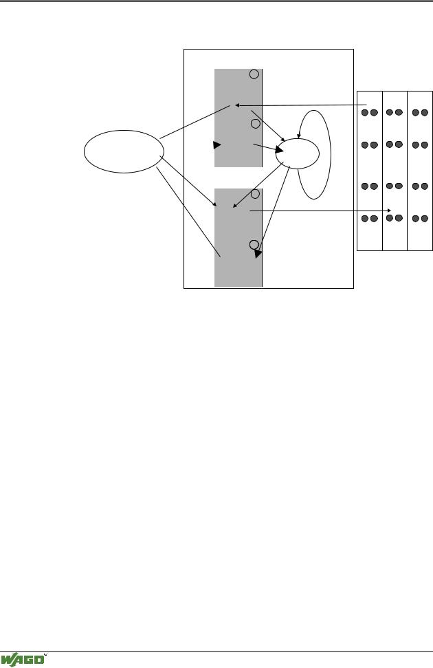
Fig. 3-26: Memory areas and data exchange for a fieldbus controller |
g012938e |
In the memory space word 0 ... 255, the controller process image contains the physical data of the bus modules.
(1)The data of the input modules can be read by the CPU and from the fieldbus side.
(2)In the same manner, writing on the output modules is possible from the CPU and from the fieldbus side. The value of the master is put out on the output while writing on an output.
The PFC variables are filed in the memory space Word 256 ... 511 of the process image.
The PFC input variables are written in the input memory space from the fieldbus side and read by the CPU for further processing.
The variables processed by the CPU via the IEC 61131-3 program are filed in the output memory space and can be read out by the master.
In addition, with the ETHERNET TCP/IP controller all output data are mirror imaged on a memory space with the address offset 0x0200 which allows to read back output values by adding 0x0200 to the MODBUS address.
Modular I/O System
ETHERNET TCP/IP