Материал: m012900e
72 • Fieldbus controller 750-842
Data exchange
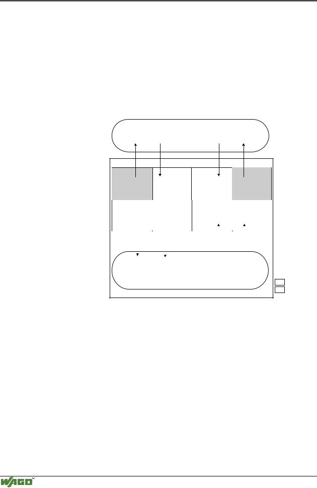
3.2.5.5Data exchange between master and PLC functionality (CPU)
The MODBUS master and the PLC functionality (CPU) of the PFC regard the data in a different manner.
Variables data created by the master reach the PFC as input variables and are further treated there.
Data created in the PFC is sent to the master through the fieldbus as output variables.
In the PFC the system can access the variable’s data as from I/O word address 256 (double word address 128, byte address 512).
MODBUS master
PII |
|
PIO |
PII |
0x000 |
0x100 |
0x000 |
0x100 |
|
(0x300) |
(0x200) |
|
Data from point of view |
|
|
|
|
|
I/O modules |
|
variables |
|
|||||||
I/O modules |
|
|
variables |
|
||||||||||||
of MODBUS master |
|
|
||||||||||||||
|
|
|
|
0x1FF |
0x0FF |
|
|
0x1FF |
|
|||||||
|
|
0x0FF |
|
|
|
|
||||||||||
|
|
|
|
|
|
(0x3FF) |
(0x2FF) |
|
|
|
|
|
||||
|
|
|
|
|
|
|
|
|
|
|
|
|
|
|
|
|
|
|
%IW0 |
|
%IW256 |
%QW0 |
|
|
%QW256 |
|
|
|
|||||
Data from point of view |
I/O modules |
|
variables |
I/O modules |
|
|
variables |
|
|
|
||||||
of PLC functionality |
|
|
|
|
|
|
||||||||||
|
|
|
|
|
|
|
|
|
|
|
|
|
|
|
||
|
|
|
|
|
|
|
|
|
|
|
|
|
|
|
|
|
|
|
%IW255 |
|
|
|
%IW511 |
%QW255 |
|
|
|
|
|
%QW511 |
|
|
|
|
|
|
|
|
|
|
|
|
|
|
||||||
|
|
|
SPS-PII |
|
|
|
SPS-PIO |
|
|
|
|
|
||||
|
|
|
|
|
|
|
|
|
|
|
|
|
|
|
|
|
|
|
|
|
|
|
|
|
|
|
|
|
|
|
|
||
|
|
|
Inputs |
|
|
|
Outputs |
|
|
|
|
|
||||
|
|
|
PLC functionality (CPU) |
|
||||||||||||
|
|
|
|
|
|
|
|
|
|
|
|
|
|
|
|
|
|
|
|
|
|
|
|
|
|
|
|
|
|
|
|
PII |
= Process Input |
|
|
|
|
|
|
|
|
|
|
|
|
|
|
|
|
Image |
|
|
|
|
|
|
|
|
|
|
|
|
|
|
|
PIO |
= Process Output |
|
|
|
|
|
|
|
|
|
|
|
|
|
|
|
|
Image |
|
|
|
Programmable Fieldbus Controller |
|
|
|
|
|
||||||||
Fig. 3-29: Data exchange between MODBUS master and PLC functionality |
g012944e |
|||||||||||||||
Data access by the MODBUS master
The data can only be accessed by the MODBUS master either word by word or bit by bit.
Addressing the data from the bus modules starts with word 0 for a word- by-word access, and also with 0 in word 0 for bit 0 for a bit-by-bit access.
Addressing the data from the variables starts with word 256 for a word-by- word access, and then, with a bit-by-bit access, addressing starts from:
4096 for bit 0 in word 256
4097 for bit 1 in word 256
...
8191 for bit 15 in word 511.
Modular I/O System
ETHERNET TCP/IP

Fieldbus controller 750-842 • 73
Data exchange
The bit number can be defined using the following formula:
BitNo = (Word * 16) + Bitno_in_Word
Data access by the PLC functionality
When accessing the same data, the PLC functionality of the PFCs uses a different type of addressing.
When declaring 16 bit variables, the PLC addressing is identical to the addressing of the MODBUS master made word-by-word.
When declaring Boolean variables (1 bit) a notation different to that of the MODBUS is used.
The bit address is composed of the elements word address and bit number in the word, separated by a dot.
Example:
Bit access MODBUS to bit number 4097 => bit addressing in the PLC <Wordno>.<Bitno> = 0.1
The PLC functionality of the PFC can also access the data byte-by-byte and double word-by-double word.
With the bytewise access, the addresses are computed according to the following formula:
High-Byte Address = Word address*2 Low-Byte Address = (Word address*2) + 1
With the access by a double word, the address is computed according to the following formula:
Double word address = High word address/2 (rounded off) or = Low word address/2
3.2.5.6Common access of MODBUS master and PLC functionality to outputs
The process illustration of outputs is described both by the MODBUS master as well as by the PLC functionality, so that the I/O module outputs can be set or reset from both sides. Design the user programs of the MODBUS master and the PLC functionality such that conflicting instructions for simultaneous setting or resetting of outputs is excluded.
Modular I/O System
ETHERNET TCP/IP
74 • Fieldbus controller 750-842
Data exchange
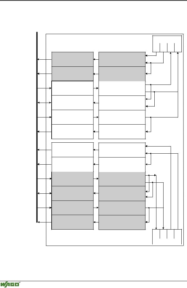
3.2.5.7Address review
MODBUS |
|
|
MODBUS addresses |
||
hex |
dec |
|
0x000 |
0 |
|
0x0FF |
255 |
|
0x000 ... 0x00F |
0 ... 15 |
|
0x0F0 ... 0X0FF |
240 |
... 255 |
0x000 |
0 |
|
0x0FF |
255 |
|
0x200 |
512 |
|
0x2FF |
767 |
|
0x000 ... 0x00F |
0 ... 15 |
|
0x0F0 ... 0X0FF |
240 ... 255 |
|
0x200 ... 0x20F |
512 ... 527 |
|
0x2F0 ... 0X2FF |
752 ... 767 |
|
0x100 |
256 |
|
0x1FF |
511 |
|
0x1000 ... 0x100F |
4096 ... 4111 |
|
0x1FF0 ... 0x1FFF |
8176 ... 8191 |
|
0x100 |
256 |
|
0x1FF |
511 |
|
0x300 |
768 |
|
0x3FF |
1023 |
|
0x1000 ... 0x100F 4096 ... 4111 |
||
0x1FF0 ... 0x1FFF 8176 ... 8191 |
||
0x2000 ... 0x200F |
8192 ... 8207 |
|
0x2FF0 ... 0x2FFF |
12272 ... 12287 |
|
|
I/O modules |
|
750-4xx....6xx |
PLC addresses |
AI DI AO DO |
%IB0, %IW0, %ID0, %IX0.0 |
PII |
%IB511, %IW255, %ID127, %IX255.15 |
%IB0+x, %IW0+x, %ID0+x, IX0+x.0 |
%IB31+x, %IW15+x, %ID7+x, %IX15+x.15 |
Digital PII |
%QB0, %QW0, %QD0, %QX0.0 |
PIO |
%QB511, %QW255,%QD127,%QX255.15 |
%QB0, %QW0, %QD0, %QX0.0 |
PIO |
%QB511,%QW255,%QD127, %QX255.15 |
%QB0+x, %QW0+x, %QD0+x, %QX0+x.0 |
%QB31+x,%QW15+x, %QD7+x, %QX15+x.15 |
Digital PIO |
%QB0+x, %QW0+x, %QD0+x, QX0+x.0 |
%QB31+x,%QW15+x,%QD7+x,%QX15+x.15 |
Digital PIO |
%QB512,%QW256, %QD128, %QX256.0 |
PLC PIO
%QB1023,%QW511,%QD255,%QX511.1
%QB512,%QW256, %QD128, %QX256.0
PLC PIO
%QB1023,%QW511,%QD255,%QX511.15
%IB512, %IW256, %ID128, %IX256.0
PLC PII
%IB1023, %IW511, %ID255, %IX511.15
%IB512, %IW256, %ID128, %IX256.0
PLC PII
%IB1023, %IW511, %ID255, %IX511.15
%IB512, %IW256, %ID128, %IX256.0
PLC PII
%IB1023, %IW511, %ID255, %IX511.15
%IB512, %IW256, %ID128, %IX256.0
PLC PII
%IB1023, %IW511, %ID255, %IX511.15
x: depending on the number of connected analog I/O modules |
AI DI AO DO |
|||
|
Controller 750-842 |
|
|
|
|
|
PLC functionality |
||
|
|
|
|
|
PLC = Programmable |
PII = Process Input Image |
AI = Analog Inputs |
AO = Analog Outputs |
|
Logic Controller |
PIO = Process Output Image |
DI = Digital Inputs |
DO = Digital Outputs |
|
|
fieldbus node |
|
|
|
Fig. 3-30: Address review, controller |
|
g012932e |
||
Modular I/O System
ETHERNET TCP/IP

Fieldbus controller 750-842 • 75
Starting up ETHERNET TCP/IP fieldbus nodes
3.2.6Starting up ETHERNET TCP/IP fieldbus nodes
This chapter shows the step-by-step procedure for starting up a
WAGO ETHERNET TCP/IP fieldbus node. The following also contains a description of how to view the controller-internal HTML pages.
Following this, information regarding PFC programming with
WAGO-I/O-PRO 32 are shown.
Attention
This description is given as an example and is limited to the execution of a local startup of an individual ETHERNET fieldbus node with a computer running under windows which is not connected to a network.
Direct Internet connection should only be performed by an authorized network administrator and is, therefore, not described in this manual.
The procedure contains the following steps:
1.Noting the MAC-ID and establishing the fieldbus node
2.Connecting the PC and fieldbus node
3.Determining the IP address
4.Allocation of the IP address to the fieldbus node
5.Function of the fieldbus tests
6.Viewing the HTML pages
3.2.6.1Note the MAC-ID and establish the fieldbus node
Before establishing your fieldbus node, please note the hardware address (MAC-ID) of your ETHERNET fieldbus controller.
This is located on the rear of the fieldbus controller and on the self-adhesive tear-off label on the side of the fieldbus controller.
MAC-ID of the fieldbus controller: |
----- ----- ----- ----- ----- -----. |
3.2.6.2Connecting PC and fieldbus node
Connect the assembled ETHERNET TCP/IP fieldbus node via a hub or directly to the PC using a 10Base-T cable.
Attention
For a direct connection, a “crossover” cable is required instead of a parallel cable.
Now start the PC, functioning as master and BootP server, and apply power to the fieldbus coupler (DC 24 V power pack). Once the operating voltage has been switched on, the initialization starts. The fieldbus controller determines the configuration of the bus modules and creates the process image.
During the startup the 'I/O' LED (Red) flashes at high frequency.
When the 'I/O' LED and the 'ON' LED light up green, the fieldbus controller is ready for operation.
If an error has occurred during startup, it is indicated as an error code by the 'I/O'-LED flashing (red).
Modular I/O System
ETHERNET TCP/IP

76 • Fieldbus controller 750-842
Starting up ETHERNET TCP/IP fieldbus nodes
3.2.6.3Determining IP addresses
If your PC is already connected to an ETHERNET network, it is very easy to determine the IP address of your PC. To do this, proceed as follows:
1.Go to the Start menu on your screen, menu item Settings and click on Control Panel.
2.Double click the icon Network.  The network dialog window will open.
3.- Under Windows NT: Select the register: Protocols and mark
the entry TCP/IP protocol.
- Under Windows 9x: Select the register: Configuration and mark the entry TCP/IP network card.
Attention
If the entry is missing, please install the respective TCP/IP component and restart your PC. The Windows-NT installation CD, or the installations CD for Windows 9x is required for the installation.
4.Subsequently, click the button "Properties...".
The IP address and the subnet mask are found in the ‘IP address’ tab.If applicable, the gateway address of your PC is found in the ‘Gateway’ tab.
5.Please write down the values:
IP address PC: |
----- . ----- |
. ----- |
. ----- |
Subnet mask: |
----- . ----- |
. ----- |
. ----- |
Gateway: |
----- . ----- |
. ----- |
. ----- |
6. Now select a desired IP address for your fieldbus node.
Attention
When selecting your IP address, ensure that it is in the same local network in which your PC is located.
7. Please note the IP address you have chosen:
IP address fieldbus node: |
----- . ----- |
. ----- |
. ----- |
3.2.6.4Allocating the IP address to the fieldbus node
A prerequisite for a communication with the controller is the assignment of an IP address.
The address can be transferred through BootP or a PFC program. With the PFC program, this is possible in WAGO-I/O-PRO 32 using the library function "ETHERNET Set-Network-Config".
Modular I/O System
ETHERNET TCP/IP