Материал: m012900e
2 • Important comments Scope
1.2 Scope
This manual describes the field bus independent WAGO-I/O-SYSTEM 750 with the fieldbus coupler for ETHERNET TCP/IP along with the programmable fieldbus controller for ETHERNET TCP/IP.
Item-No.
750-342
750-842
750-4xx...6xx
Components
EtherNet TCP/IP 10 Mbit
Contr. EtherNet TCP/IP TCP 10 Mbit
I/O Modules
1.3 Symbols
Danger
Always observe this information to protect persons from injury.
Warning
Always observe this information to prevent damage to the device.
Attention
Marginal conditions must always be observed to ensure smooth operation.
ESD (Electrostatic Discharge)
Warning of damage to the components by electrostatic discharge. Observe the precautionary measure for handling components at risk.
Note
Routines or advice for efficient use of the device and software optimization.
More information
i References to additional literature, manuals, data sheets and INTERNET pages.
Modular I/O System
ETHERNET TCP/IP

Important comments • 3
Font conventions
1.4 Font conventions
Italic
Italic
\
Names of paths and files are marked in italic. i. e.: C:\programs\WAGO-I/O-CHECK
Menu items are marked in bold italic. i. e.: Save
A backslash between two names markes a sequence of menu items.
i. e.: File\New
END
< >
Courier
Keys to press are marked in bold with small capitals. i. e.: ENTER
Keys are marked bold within angle brackets. i. e.: <F5>
Program codes are printed with the font Courier. i. e.: END_VAR
1.5 |
Number notation |
|
|
||
|
|
|
|
|
|
|
|
|
Number code |
Example |
Code |
|
|
|
Decimal |
100 |
normal notation |
|
|
|
|
|
|
|
|
|
Hexadecimal |
0x64 |
C notation |
|
|
|
|
|
|
|
|
|
Binary |
’100’ |
Within ’, |
|
|
|
|
’0110.0100’ |
Nibble separated with dots |
|
|
|
|
|
|
1.6 |
Abbreviation |
|
|
||
|
|
|
AI |
Analog Input |
|
|
|
|
AO |
Analog Output |
|
|
|
|
DI |
Digital Input |
|
|
|
|
DO |
Digital Output |
|
|
|
|
I/O |
Input/Output |
|
|
|
|
ID |
Identifier |
|
|
|
|
PFC |
Programmable Fieldbus Controller |
|
Modular I/O System
ETHERNET TCP/IP
4 • The WAGO-I/O-SYSTEM 750
System Description
2 The WAGO-I/O-SYSTEM 750
2.1 System Description
2.1.1General
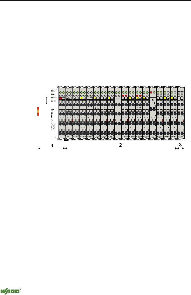
The WAGO-I/O-SYSTEM consists of various components which are capable of providing modular and application specific fieldbus nodes for various fieldbusses.
A fieldbus node (short: Node) consists in principle of a fieldbus coupler (short: Coupler) or a programmable fielbus controller (short: Controller) at the front end (1), a number of I/O modules (2) and an end module (3) which is placed at the other end.
|
|
|
|
|
|
|
|
|
|
|
|
|
|
|
|
|
|
|
|
|
|
|
|
|
|
|
|
|
|
|
|
|
|
|
|
|
|
|
|
|
|
|
|
|
|
|
|
|
|
|
|
|
|
|
|
|
|
|
|
|
|
|
|
|
|
|
|
|
|
|
|
|
|
|
|
|
|
|
|
|
|
|
|
|
|
|
|
|
|
|
|
|
|
|
|
|
|
|
|
|
|
|
|
|
|
|
|
|
|
|
|
|
|
|
|
|
|
|
|
|
|
|
|
|
|
|
|
|
|
|
|
|
|
|
|
|
|
|
|
|
|
|
|
|
|
|
|
|
|
|
|
|
|
|
|
|
|
|
|
|
|
|
|
|
|
|
|
|
|
|
|
|
|
|
|
|
|
|
|
|
|
|
|
|
|
|
|
|
|
|
|
|
|
|
|
|
|
|
|
|
|
|
|
|
|
|
|
|
|
|
|
|
|
|
|
|
|
|
|
|
|
|
|
|
|
|
|
|
|
|
|
|
|
|
|
|
|
|
|
|
|
|
|
|
|
|
|
|
|
|
|
|
|
|
|
|
|
|
|
|
|
|
|
|
|
|
|
|
|
|
|
|
|
|
|
|
|
|
|
|
|
|
|
|
|
|
|
|
|
|
|
|
|
|
|
|
|
|
|
|
|
|
|
|
|
|
|
|
|
|
|
|
|
|
|
|
|
|
|
|
|
|
|
|
|
|
|
|
|
|
|
|
|
|
|
|
|
|
|
|
|
|
|
|
|
|
|
|
|
|
|
|
|
|
|
|
|
|
|
|
|
|
|
|
|
|
|
|
|
|
|
|
|
|
|
|
|
|
|
|
|
|
|
|
|
|
|
|
|
|
|
|
|
|
|
|
|
|
|
|
|
|
|
|
|
|
|
|
|
|
|
|
|
|
|
|
|
|
|
|
|
|
|
|
|
|
|
|
|
|
|
|
|
|
|
|
|
|
|
|
|
|
|
|
|
|
|
|
|
|
|
|
|
|
|
|
|
|
|
|
|
|
|
|
|
|
|
|
|
|
|
|
|
|
|
|
|
|
|
|
|
|
|
|
|
|
|
|
|
|
|
|
|
|
|
|
|
|
|
|
|
|
|
|
|
|
|
|
|
|
|
|
|
|
|
|
|
|
|
|
|
|
|
|
|
|
|
|
|
|
|
|
|
|
|
|
|
|
|
|
|
|
|
|
|
|
|
|
|
|
|
|
|
|
|
|
|
|
|
|
|
|
|
|
|
|
|
|
|
|
|
|
|
|
|
|
|
|
|
|
|
|
|
|
|
|
|
|
|
|
|
|
|
|
|
|
|
|
|
|
|
|
|
|
|
|
|
|
|
|
|
|
|
|
|
|
|
|
|
|
|
|
|
|
|
|
|
|
|
|
|
|
|
|
|
|
|
|
|
|
|
|
|
|
|
|
|
|
|
|
|
|
|
|
|
|
|
|
|
|
|
|
|
|
|
|
|
|
|
|
|
|
|
|
|
|
|
|
|
|
|
|
|
|
|
|
|
|
|
|
|
|
|
|
|
|
|
|
|
|
|
|
|
|
|
|
|
|
|
|
|
|
|
|
|
|
|
|
|
|
|
|
|
|
|
|
|
|
|
|
|
|
|
|
|
|
|
|
|
|
|
|
|
|
|
|
|
|
|
|
|
|
|
|
|
|
|
|
|
|
|
|
|
|
|
|
|
|
|
|
|
|
|
|
|
|
|
|
|
|
|
|
|
|
|
|
|
|
|
|
|
|
|
|
|
|
|
|
|
|
|
|
|
|
|
|
|
|
|
|
|
|
|
|
|
|
|
|
|
|
|
|
|
|
|
|
|
|
|
|
|
|
|
|
|
|
|
|
|
|
|
|
|
|
|
|
|
|
|
|
|
|
|
|
|
|
|
|
|
|
|
|
|
|
|
|
|
|
|
|
|
|
|
|
|
|
|
|
|
|
|
|
|
|
|
|
|
|
|
|
|
|
|
|
|
|
|
|
|
|
|
|
|
|
|
|
|
|
|
|
|
|
|
|
|
|
|
|
|
|
|
|
|
|
|
|
|
|
|
|
|
|
|
|
|
|
|
|
|
|
|
|
|
|
|
|
|
|
|
|
|
|
|
|
|
|
|
|
|
|
|
|
|
|
|
|
|
|
|
|
|
|
|
|
|
|
|
|
|
|
|
|
|
|
|
|
|
|
|
|
|
|
|
|
|
|
|
|
|
|
|
|
|
|
|
|
|
|
|
|
|
|
|
|
|
|
|
|
|
|
|
|
|
|
|
|
|
|
|
|
|
|
|
|
|
|
|
|
|
|
|
|
|
|
|
|
|
|
|
|
|
|
|
|
|
|
|
|
|
|
|
|
|
|
|
|
|
|
|
|
|
|
|
|
|
|
|
|
|
|
|
|
|
|
|
|
|
|
|
|
|
|
|
|
|
|
|
|
|
|
|
|
|
|
|
|
|
|
|
|
|
|
|
|
|
|
|
|
|
|
|
|
|
|
|
|
|
|
|
|
|
|
|
|
|
|
|
|
|
|
|
|
|
|
|
|
|
|
|
|
|
|
|
|
|
|
|
|
|
|
|
|
|
|
|
|
|
|
|
|
|
|
|
|
|
|
|
|
|
|
|
|
|
|
|
|
|
|
|
|
|
|
|
|
|
|
|
|
|
|
|
|
|
|
|
|
|
|
|
|
|
|
|
|
|
|
|
|
|
|
|
|
|
|
|
|
|
|
|
|
|
|
|
|
|
|
|
|
|
|
|
|
|
|
|
|
|
|
|
|
|
|
|
|
|
|
|
|
|
Fig. 2-1: Setting up a fieldbus node with the WAGO-I/O-SYSTEM |
|
|
|
|
|
|
|
|
|
|
|
|
|
|
|
|
|
g012900x |
|||||||||||||||||||||||||||||||||||||||||
2.1.2Coupler/Controller (1)
The Coupler/Controller forms the link between the fieldbus and the field devices with their I/O functions. All control functions required for the faultless operation of the I/O functions are carried out by the Coupler/Controller. The connection to different fieldbus systems is established by each of the corresponding Coupler/Controller, e.g. for PROFIBUS, INTERBUS, CAN, MODBUS etc. In this way a change of the fieldbus system is possible.
The programmable fieldbus controller 750-842 combines the ETHERNET TCP/IP functionality of the fieldbus coupler 750-342 with the functionality of a Programmable Logic Control (PLC). Programming of the application is done with WAGO-I/O-PRO in accordance with IEC 61131-3, covering all 5 programming languages. The programmer can access all fieldbus and I/O data.
Modular I/O System
ETHERNET TCP/IP

The WAGO-I/O-SYSTEM 750 • 5
System Description
Characteristics and use of the Controllers:
•The use of decentralized control can better support a PLC or PC
•Complex applications can be divided into multiple tasks
•Programmable response in the event of a fieldbus failure
•Signal pre-processing reduces fieldbus transmissions
•Peripheral equipment can be controlled directly, resulting in faster system response times
•Simple, self-sufficient control
2.1.3I/O Modules (2)
In the I/O modules, the incoming process data is converted. Corresponding to the different requirements, special I/O modules are available for a variety of functions. There are digital and analog inputs and outputs and modules for special functions (Counter modules, Terminal blocks for encoder and resolvers and communication modules).
2.1.4End Module (3)
An End Module is needed for faultless operation of the node. The termination module is always placed as the last module in order to obtain a termination of the fieldbus node. This module has no I/O function.
Modular I/O System
ETHERNET TCP/IP
6 • The WAGO-I/O-SYSTEM 750
Installation
2.2 Installation
2.2.1Safty notes
ESD (Electrostatic Discharge)
The modules are equipped with electronic components which may be destroyed by electrostatic discharge.When handling the modules, ensure that the environment (persons, workplace and packing) is well grounded. Avoid touching conductive components, e.g. gold contacts.
Attention
Switch off the system prior to working on bus modules!
2.2.2Mechanical Installation
All system components can be snapped directly on a carrier rail in accordance with the European standard EN 50022 (DIN 35).
Attention
Ensure that the carrier rail is fastened with countersunk head screws or blind rivets as the snap-on foot of the I/O components extends onto the carrier rail.
The installation is simple and space saving. All modules have the same shape to minimize the project commitment.
The reliable positioning and connection of the coupler and the individual I/O modules is made using a tongue and groove system. Due to the automatic locking, the individual components are securely seated on the rail after installing.
Modular I/O System
ETHERNET TCP/IP