Материал: m012900e
The WAGO-I/O-SYSTEM 750 • 7
Installation
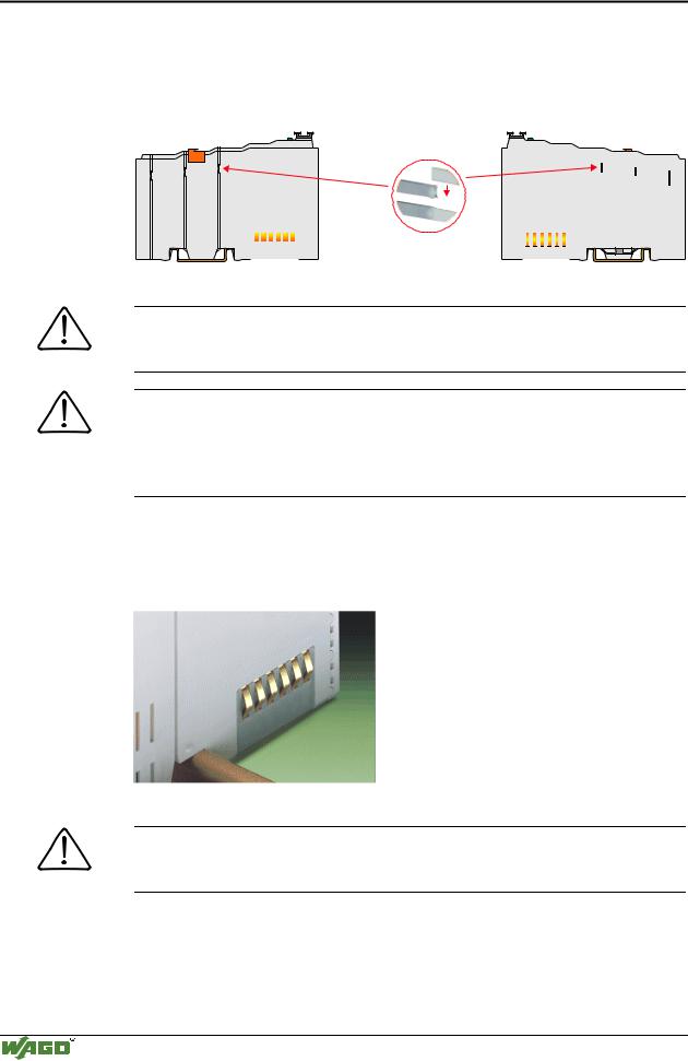
To secure the coupler/controller against moving sideways, lock it with the orange colored locking disc on the carrier rail. To lock, insert a screwdriver into the top groove of the locking disc and press.
To pull out the fieldbus coupler, release the locking disc by pressing on the bottom groove with a screwdriver and then pull the orange colored unlocking lug.
Fig. 2-2: Coupler/Controller and unlocking lug |
G012912d |
It is also possible to release an individual I/O module from the unit by pulling the unlocking lug.
Fig. 2-3: Releasing a I/O Module |
p0xxx01x |
Danger
Ensure that an interruption of the ground will not result in a condition which could endanger a person or equipment!
Modular I/O System
ETHERNET TCP/IP
8 • The WAGO-I/O-SYSTEM 750
Installation
Self-cleaning power jumper contacts conduct the supply voltage for the field side. They are located on either side of the modules. The female contacts on the right-hand side of the fieldbus coupler and the bus modules are designed as spring contacts to protect against accidental contact. Male contacts are located on the left-hand side of the bus modules.
Pos. 1
Pos. 2
|
|
|
|
|
|
|
|
|
|
|
|
|
|
|
|
|
|
|
|
|
|
|
|
|
|
|
|
|
|
|
|
|
|
|
|
|
|
|
|
Fig. 2-4: Power Jumper Contacts |
|
|
|
|
|
|
|
g01xx00d |
|
Danger
The power contacts have sharp-edges. Handle the module carefully to prevent injury.
Attention
Please take into consideration that some bus modules have no or only some power jumper contacts. The design of some modules does not physically allow for assembling them in rows as the grooves for the male contacts are closed at the top.
The data contacts are designed as self-cleaning gold spring contacts which automatically produce a secure connection.
Fig. 2-5: Data contacts |
p0xxx07x |
Warning
Do not connect the I/O module to gold spring contacts in order to avoid tarnishing or scratching!
Modular I/O System
ETHERNET TCP/IP
The WAGO-I/O-SYSTEM 750 • 9
Electrical Installation
2.3 Electrical Installation
2.3.1Wire Connection
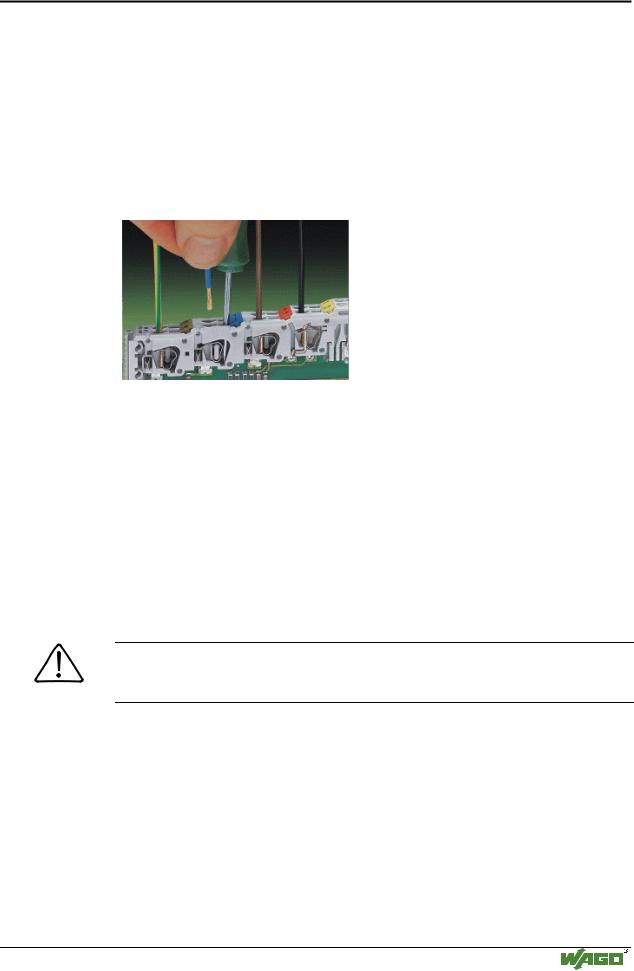
Conductors with a cross section of 0.08 to 2.5 mm² (AWG 28-12) can be connected using a CAGE CLAMP connection to achieve a vibration resistant, fast and maintenance free connection. To actuate CAGE CLAMP enter an actuation tool in the opening above the connection. Following this, enter the conductor in the corresponding opening. The conductor is clamped securely with the removal of the actuation tool.
Fig. 2-6: Inserting conductor end |
p0xxx06x |
The clamping force adjusts automatically to the cross section. The full surface of the CAGE CLAMP pressure is applied against the conductor without damaging it. Conductor deformation is compensated for and self-loosening is avoided. The transition point between the conductor and the CAGE CLAMP is protected against corrosive influences. The connection can be made quickly and is also maintenance free, saving the costs for a periodic checking of terminal connections.
Two carrier rail contacts responsible for the electrical contact between the grounded carrier rail and the controller are fitted underneath the coupler/controller.
Attention
Ensure a perfect contact point between carrier rail contacts and carrier rail. The carrier rail must be grounded.
Modular I/O System
ETHERNET TCP/IP
10 • The WAGO-I/O-SYSTEM 750
Electrical Installation
2.3.2Change fuse
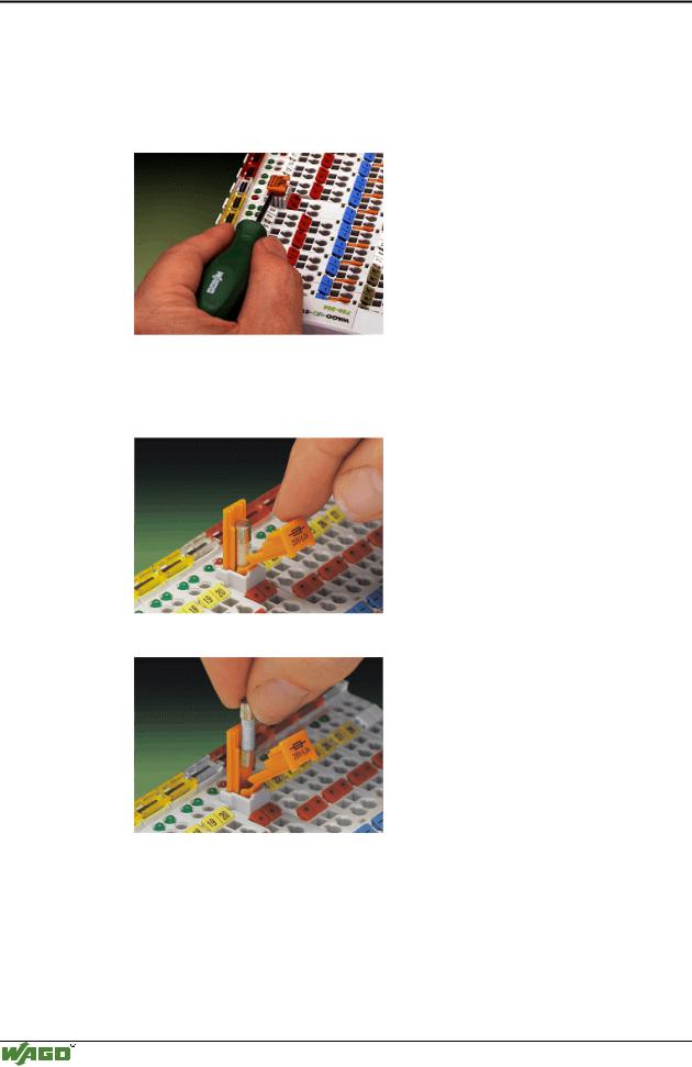
Some Power supply modules of the WAGO-I/O-SYSTEM 750 are equipped with a fuse holder. To isolate the modules to the right of the power supply, the fuse can be removed from the fuse holder. For this insert a screw driver into one of the slits available on each side and lift the holder.
Fig. 2-7: Removing the fuse holder |
p0xxx05x |
The fuses can be removed from or inserted into the fuse holder cover. Then push the fuse holder back into the original position.
Fig. 2-8: Opening the fuse holder |
p0xxx03x |
Fig. 2-9: Change fuse |
p0xxx04x |
Modular I/O System
ETHERNET TCP/IP
The WAGO-I/O-SYSTEM 750 • 11
Power supply
2.4 Power supply
1 |
|
|
750-400 |
750-410 |
750-403 |
2
-612 |
750-512 |
750-512 |
750-513 |
750-616 |
750-454 |
750-467 |
750-461 |
750-550 |
-610 |
750-552 |
750-630 |
750-650 |
750-600 |
|
~ |
|
24V 24V |
230V |
24V |
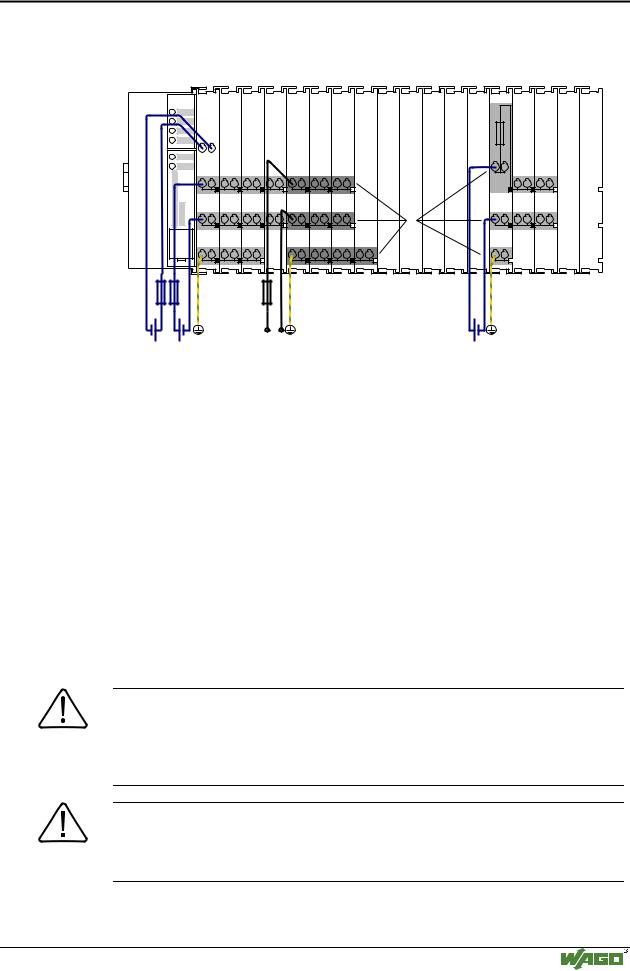
Fig. 2-10: Power supply |
|
g01xx02x |
1 – Power supply System
2 – Power supply Field-side
The power supply on the field side is electrically isolated from the system supply. In this manner sensors and actuators can be supplied and fused by a separate voltage source.
If a non-regulated power supply is used for the coupler/controller electronics 24 V voltage supply, it must be filtered through a capacitor (200 µF per 1 A load current). A back-up capacitor module (Order-No. 288-824) was developed for the WAGO-I/O-SYSTEM. This module serves to regulate a noisy 24 V DC voltage supply and to keep the ripple voltage within specified limits. These fluctuations could be caused by a voltage interruption on the primary
side, a secondary side overload or the switching of ”non quenched“ inductance or capacitance.
Warning
The supply module’s + and –, which are permanently integrated on the buscouplers, must be supplied with 24 V DC only.
120 V AC and 230 V AC can only be supplied via modules 750-609, 750-611 and 750-612!
Warning
The ground (earth) field side contact should be disconnected when testing the isolation. Otherwise the results could be wrong or the module could be destroyed.
Modular I/O System
ETHERNET TCP/IP