Материал: m012900e
Fieldbus coupler / controller • 17
Fieldbus coupler 750-342
3 Fieldbus coupler / controller
3.1 Fieldbus coupler 750-342
This chapter includes:
3.1.1 |
Description ..................................................................................... |
18 |
3.1.2 |
Hardware ........................................................................................ |
19 |
3.1.2.1 |
View......................................................................................... |
19 |
3.1.2.2 |
Device supply .......................................................................... |
20 |
3.1.2.3 |
Fieldbus connection ................................................................. |
20 |
3.1.2.4 |
Display elements...................................................................... |
21 |
3.1.2.5 |
Configuration interface ............................................................ |
21 |
3.1.2.6 |
Hardware address (MAC-ID) .................................................. |
21 |
3.1.3 |
Operating system ............................................................................ |
22 |
3.1.4 |
Process image ................................................................................. |
23 |
3.1.4.1 |
Example of a process input image ........................................... |
24 |
3.1.4.2 |
Example of a process output image ......................................... |
25 |
3.1.4.3 |
Process data architecture for MODBUS/TCP ......................... |
26 |
3.1.5 |
Data exchange................................................................................. |
31 |
3.1.5.1 |
Memory areas .......................................................................... |
32 |
3.1.5.2 |
Addressing ............................................................................... |
32 |
3.1.5.3 |
Data exchange between MODBUS master and I/O modules .. |
34 |
3.1.6 |
Starting up ETHERNET TCP/IP fieldbus nodes............................ |
35 |
3.1.6.1 |
Note the MAC-ID and establish the fieldbus node.................. |
35 |
3.1.6.2 |
Connecting PC and fieldbus node............................................ |
35 |
3.1.6.3 |
Determining IP addresses ........................................................ |
36 |
3.1.6.4 |
Allocating the IP address to the fieldbus node ........................ |
36 |
3.1.6.5 |
Testing the function of the fieldbus node ................................ |
39 |
3.1.6.6 |
Reading out the information as HTML pages.......................... |
40 |
3.1.7 |
LED Display ................................................................................... |
41 |
3.1.7.1 |
Blink code................................................................................ |
41 |
3.1.7.2 |
Fieldbus status ......................................................................... |
42 |
3.1.7.3 |
Node status............................................................................... |
42 |
3.1.7.4 |
Fault message via blink code from the I/O-LED ..................... |
43 |
3.1.8 |
Fault behavior ................................................................................. |
45 |
3.1.8.1 |
Fieldbus failure ........................................................................ |
45 |
3.1.8.2 |
Internal bus fault ...................................................................... |
45 |
3.1.9 |
Technical Data................................................................................ |
46 |
Modular I/O System
ETHERNET TCP/IP

18 • Fieldbus coupler 750-342 Description
3.1.1Description
The fieldbus coupler 750-342 displays the peripheral data of all I/O modules in the WAGO-I/O-SYSTEM 750 on ETHERNET.
All sensor input signals are grouped in the coupler (slave) and transferred to the higher ranking controls (master) via the fieldbus. Process data linking is performed in the higher ranking controls. The controls put out the resulting data to the actuators via the bus and the node.
To be able to transmit process data via ETHERNET, the coupler supports a series of network protocols. Process data are exchanged with the aid of the MODBUS/TCP protocol.
Once the ETHERNET TCP/IP fieldbus coupler is connected, the coupler detects all I/O modules connected to the node and creates a local process image on this basis, which can be a mixed arrangement of analog (word-by-word data exchange) and digital (bit-by-bit data exchange) modules.
The local process image is subdivided into an input and an output data area.
The data of the analog modules are mapped into the process image in the order of their position downstream of the bus coupler.
The bits of the digital modules are grouped into words and also mapped into the process image as soon as mapping of the analog modules is completed. When the number of digital I/O’s exceeds 16 bits, the coupler automatically starts the next word.
Also note that all process images start at WORD 0.
Information on configuration, status and the I/O data of the fieldbus node are stored in the fieldbus coupler as HTML pages. These pages can be seen via a standard WEB browser by typing the IP address, that you assigned the coupler, into the Address field of your web browser.
Modular I/O System
ETHERNET TCP/IP
|
|
|
|
|
Fieldbus coupler 750-342 • 19 |
|
|
|
|
|
Hardware |
3.1.2 |
Hardware |
|
|
|
|
3.1.2.1 |
View |
|
|
|
|
|
|
ETHERNET |
01 |
02 |
status |
|
|
voltage supply |
|||
|
|
|
|
|
|
|
|
ON |
A |
|
-power jumper contacts |
|
|
|
C |
||
|
fieldbus |
LINK |
|
-system |
|
|
B |
|
|||
|
connection |
|
|
D |
|
|
TxD/RxD |
24V 0V |
data contacts |
||
|
RJ 45 |
||||
|
ERROR |
|
|
supply |
|
|
|
|
|
||
|
|
|
|
|
24V |
|
|
I/O |
|
|
0V |
|
|
+ |
+ |
|
|
|
|
|
supply via |
||
|
|
|
|
|
|
|
|
|
|
|
power jumper contacts |
|
|
|
|
|
24V |
|
|
|
- |
- |
|
|
|
-342 |
|
|
0V |
|
|
750 |
|
|
|
|
|
|
|
|
|
|
flap |
|
|
|
|
|
open |
|
|
|
|
|
configuration |
|
|
|
power jumper contacts |
|
|
|
|
|
|
|
interface |
|
|
|
|
|
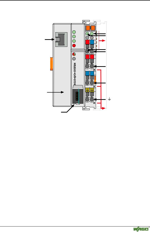
Fig. 3-1: Fieldbus coupler ETHERNET TCP/IP |
|
G034200e |
||
The fieldbus coupler is comprised of:
•Supply module which includes the internal system supply as well as power jumper contacts for the field supply via I/O module assemblies.
•Fieldbus interface with the bus connection RJ 45
•Display elements (LED’s) for status display of the operation, the bus communication, the operating voltages as well as for fault messages and diagnosis
•Configuration Interface
•Electronics for communication with the I/O modules (internal bus) and the fieldbus interface
Modular I/O System
ETHERNET TCP/IP
20 • Fieldbus coupler 750-342 Hardware
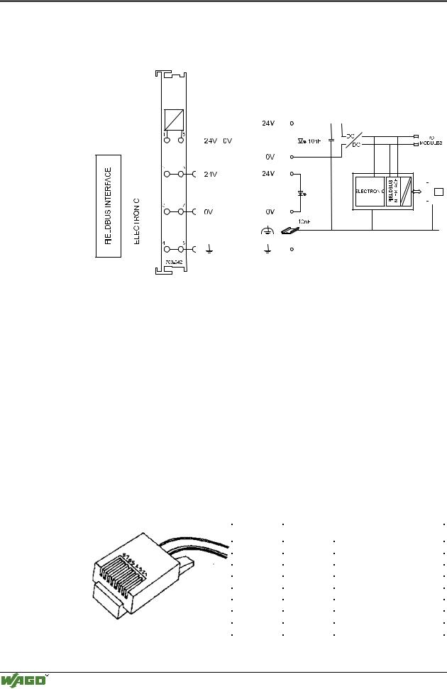
3.1.2.2Device supply
The supply is made via terminal bocks with CAGE CLAMP® connection. The device supply is intended both for the system and the field units.
|
|
|
|
|
|
|
|
|
|
|
|
|
|
|
|
|
|
|
|
|
|
|
|
|
|
|
|
|
|
|
|
|
|
|
|
|
|
|
|
|
|
|
|
|
|
|
|
|
|
|
|
|
|
|
|
|
|
|
|
|
|
|
|
|
|
|
|
|
|
|
|
|
|
|
|
|
|
|
|
|
|
|
|
|
|
|
|
|
|
|
|
|
|
|
|
|
|
|
|
|
|
|
|
|
|
|
|
|
|
|
|
|
|
|
|
|
|
|
|
|
|
|
|
|
|
|
|
|
|
|
|
|
|
|
|
|
|
|
|
|
|
|
|
|
|
|
|
|
|
|
|
|
|
|
|
|
|
|
|
|
|
|
|
|
|
|
|
|
|
|
|
|
|
|
|
|
|
|
|
|
|
|
|
|
|
|
|
|
|
|
|
|
|
|
|
|
|
|
|
|
|
|
|
|
|
|
|
|
|
|
|
|
|
|
|
|
|
|
|
|
|
|
|
|
|
|
|
|
|
|
|
|
|
|
|
|
|
|
|
|
|
|
|
|
|
|
|
|
|
|
|
|
|
|
|
|
|
|
|
|
|
|
|
|
|
|
|
|
|
|
|
|
|
|
|
|
|
|
|
|
|
|
|
|
|
|
|
|
|
|
|
|
|
|
|
|
|
|
|
|
|
|
|
|
|
|
|
|
|
|
|
|
|
|
|
|
|
|
|
|
|
|
|
|
|
|
|
|
|
|
|
|
|
|
|
|
|
|
|
|
|
|
|
|
|
|
|
|
|
|
|
|
|
|
|
|
|
|
|
|
|
|
|
|
|
|
|
|
|
|
|
|
|
|
|
|
|
|
|
|
|
|
|
|
|
|
|
|
|
|
|
|
|
|
|
|
|
|
|
|
|
|
|
|
|
|
|
|
|
|
|
|
|
|
|
|
|
|
|
|
|
|
|
|
|
|
|
|
|
|
|
|
|
|
|
|
|
|
|
|
|
|
|
|
|
|
|
|
|
|
|
|
|
|
|
|
|
|
|
|
|
|
|
|
|
|
|
|
|
|
|
|
|
|
|
|
|
|
|
|
|
|
|
|
|
|
|
|
|
|
|
|
|
|
|
|
|
|
|
|
|
|
|
Fig. 3-2: Device supply |
G034201e |
||||||||||||||||||||||||||
The integrated internal system supply module generates the necessary voltage to supply the electronics and the connected I/O modules.
The fieldbus interface is supplied with electrically isolated voltage from the internal system supply module.
3.1.2.3Fieldbus connection
Connection to the fieldbus is by an RJ45 connector. A category 5, shielded/unshielded twisted pair cable (S-UTP) with an impedance of 100 Ohm ± 15% is mandatory as a connecting line for the 10BaseT Interface.
The connection point is physically lowered for the coupler/controller to fit in an 80 mm high switch box once connected.
The electrical isolation between the fieldbus system and the electronics is achieved by means of DC/DC converters and optocouplers in the fieldbus interface.
Contact |
Signal |
|
|
|
|
1 |
TD + |
Transmit + |
2 |
TD - |
Transmit - |
3 |
RD + |
Receive + |
4 |
|
free |
5 |
|
free |
6 |
RD - |
Receive - |
7 |
|
free |
8 |
|
free |
Fig. 3-3: RJ45-connector and RJ45 connector configuration
Modular I/O System
ETHERNET TCP/IP
Fieldbus coupler 750-342 • 21
Hardware
3.1.2.4Display elements
The operating condition of the fieldbus coupler or node is signaled via light diodes (LED).
|
|
|
|
|
|
|
|
|
|
|
|
|
|
status |
|
|
ETHERNET |
|
01 |
|
|
02 |
|
|
|
|
|
|
|
||||
|
|
|
|
|
|
|
|
|
|
|||||||
|
|
|
|
|
|
|
|
|
|
|
|
|
|
voltage supply |
|
|
|
ON |
A |
|
|
|
|
|
|
|
|
|
-power jumper contacts |
|
|||
|
LINK |
B |
|
|
|
C |
|
|
|
|
|
|
||||
|
|
|
|
|
|
|
|
|
|
|||||||
|
|
|
|
|
|
D |
|
|
|
|
|
-system |
|
|||
|
|
|
|
|
||||||||||||
|
TxD/RxD |
|
24V 0V |
|
|
|
|
|
|
|
|
|||||
|
|
|
|
|||||||||||||
|
ERROR |
|
|
|
|
|
|
|
|
|
|
|
|
|
|
|
|
I/O |
|
+ |
|
+ |
|
|
|
|
|
|
|
|
|
|
|
|
|
|
|
|
|
|
|
|
|
|
|
|
||||
|
|
|
|
|
|
|
|
|
|
|
|
|
||||
|
|
|
|
|
|
|
|
|
|
|
|
|
||||
|
|
|
|
|
|
|
|
|
|
|
|
|||||
|
|
|
|
|
|
|
|
|
|
|
|
|
|
|||
|
|
|
|
|
|
|
|
|
|
|
||||||
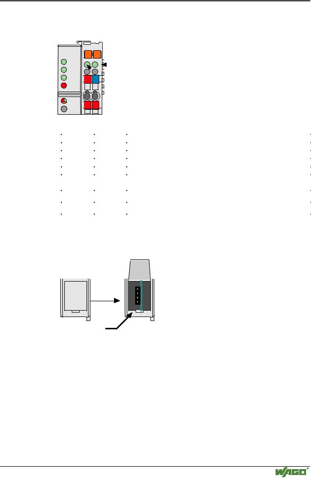
Fig. 3-4: Display elements 750-342 |
G012901e |
|||||||||||||||
|
|
|
|
|
|
|
|
|
|
|||||||
|
LED |
|
|
|
|
Color |
|
Meaning |
|
|||||||
|
ON |
|
|
|
|
green |
|
Fieldbus initialization is correct |
|
|||||||
|
LINK |
|
|
|
|
green |
|
Link to a physical network exists |
|
|||||||
|
TxD/RxD |
|
green |
|
Data exchange taking place |
|
||||||||||
|
ERROR |
|
red |
|
Error on the fieldbus |
|
||||||||||
|
IO |
|
|
|
|
red /green |
|
The ’I/O’-LED indicates the operation of the node and signals faults |
||||||||
|
|
|
|
|
|
/ orange |
|
encountered |
|
|||||||
|
A |
|
|
|
|
green |
|
Status of the operating voltage – system |
|
|||||||
|
|
|
|
|
|
|
|
|
|
|||||||
|
C |
|
|
|
|
green |
|
Status of the operating voltage – power jumper contacts |
|
|||||||
|
|
|
|
|
|
|
|
|
|
|
|
|
|
|
|
|
3.1.2.5Configuration interface
The configuration interface used for the communication with WAGO-I/O- CHECK or for firmware download is located behind the cover flap.
open flap
Configuration interface
Fig. 3-5: Configuration interface |
g012945e |
The communication cable (750-920) is connected to the 4 pole header.
3.1.2.6Hardware address (MAC-ID)
Each WAGO ETHERNET fieldbus coupler is provided from the factory with a unique and internationally unambiguous physical ETHERNET address, also referred to as MAC-ID (Media Access Control Identity). This address is to be found on the rear of the coupler and on an adhesive tear-off label on the side of the coupler. The address has a fixed length of 6 Bytes (48 Bit) and contains the address type, the manufacturer’s ID, and the serial number.
Modular I/O System
ETHERNET TCP/IP