Материал: m012900e
22 • Fieldbus coupler 750-342 Operating system
3.1.3Operating system
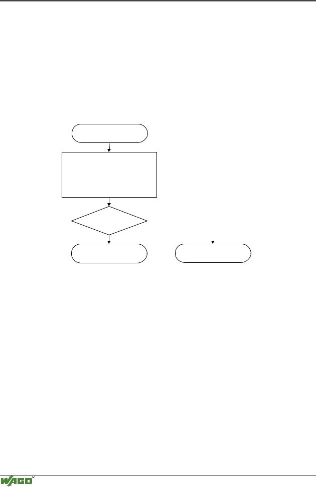
Following is the configuration of the master activation and the electrical installation of the fieldbus station to start up the system.
After switching on the supply voltage, the coupler determines the I/O modules and the present configuration.
In the event of a fault, the coupler changes to the "Stop" condition. The "I/O" LED flashes red. After a fault free start up, the coupler changes to the "Fieldbus start" status and the "I/O" LED lights up green.
Switching on the supply voltage
Initialization, Determination of the I/O modules
and the configuration,
“I/O” LED is blinking red
Test o.k.? |
No |
|
|
|
|
|
|
Yes |
|
|
|
|
Stop |
||
Fieldbus coupler is |
|
||
in operating mode |
|
red “I/O” LED indicates |
|
“I/O” LED is shining green |
|
blink code |
|
Fig. 3-6: Operating system 750-342 |
|
g012920e |
|
Modular I/O System
ETHERNET TCP/IP
Fieldbus coupler 750-342 • 23
Process image
3.1.4Process image
After switching on, the coupler recognizes all I/O modules plugged into the node which supply or wait for data (data width/bit width > 0). Analog and digital I/O modules can be mixed on the same node.
Note
For the number of input and output bits or bytes of the individually activated I/O modules, please refer to the corresponding I/O module description.
The coupler produces an internal process image from the data width and the type of I/O module as well as the position of the I/O modules in the node. It is divided into an input and an output data area.
The data of the digital I/O modules is bit orientated, i.e. the data exchange is made bit for bit. The analog I/O modules are representative for all byte orientated I/O modules, i.e. those where the data exchange is made byte for byte.
These I/O modules include for example the counter modules, I/O modules for angle and path measurement as well as the communication modules.
The data of the I/O modules is separate from the local input and output process image in the sequence of their position after the coupler in the individual process image.
First, all the byte oriented bus modules and then the bit oriented bus modules are stored in the process image. The bits of the digital modules are grouped to form bytes. As soon as the number of digital I/O’s exceeds 8 bits, the coupler automatically starts the next byte.
Note
A process image restructuring may result if a node is changed. In this case the process data addresses also change in comparison with earlier ones. In the event of adding modules, take the process data of all previous modules into account.
The coupler provides a storage area of 256 words each (word 0 - 255) for the physical input and output data.
Modular I/O System
ETHERNET TCP/IP
24 • Fieldbus coupler 750-342
Data exchange
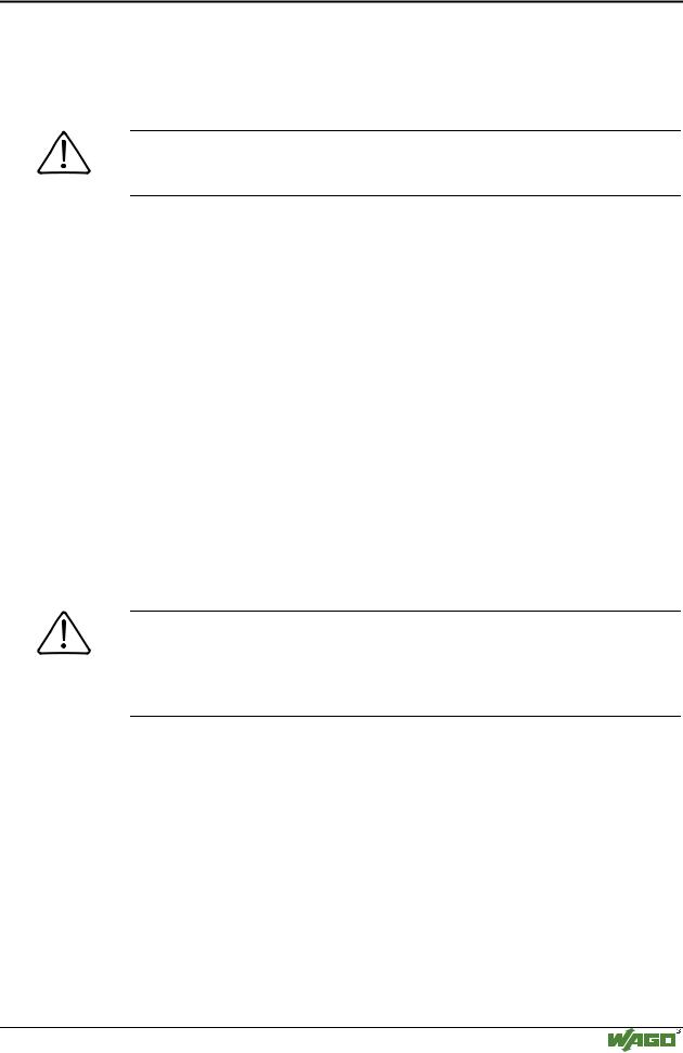
3.1.4.1Example of a process input image
The following figure is an example of a process input image. The configuration comprises of 16 digital and 8 analog inputs.
The process image thus has a data length of 8 words for the analog and 1 word for the digital inputs, i.e. 9 words in total.
Ethernet
 ON
ON
 LINK
LINK
 TxD/RxD
 ERROR
ERROR
 I/O
I/O
SY STEM |
|
W AGO /OI |
750-842 |
DI DI AI AI DI AI DI AI
Input modules 750402 |
402 |
472 472 |
402 |
476 |
402 476 |
|
|
Bit 1 |
1 |
|
1 |
|
1 |
Process input image |
|
|
Word1 Word1 |
|
Word1 |
Word1 |
Bit 4 |
4 |
Word2 Word2 |
4 |
Word2 4 |
Word2 |
|
(Word)
MODBUS addresses |
||
0x0000 |
Word1 |
|
0x0001 |
Word2 |
|
0x0002 |
Word1 |
|
0x0003 |
Word2 |
|
0x0004 |
Word1 |
|
0x0005 |
Word2 |
|
0x0006 |
Word1 |
|
0x0007 |
Word2 |
|
0x0008 |
|
|
Highbyte |
Lowbyte |
|
Process input image |
||
(Bit) |
||
MODBUS addresses |
||
0x0000 |
|
|
0x0001 |
|
|
0x0002 |
|
|
0x0003 |
|
|
0x0004 |
|
|
0x0005 |
|
|
0x0006 |
|
|
0x0007 |
|
|
0x0008 |
|
|
0x0009 |
DI: Digital Input |
|
0x000A |
||
AI:Analog Input |
||
0x000B |
||
|
||
0x000C |
|
|
0x000D |
|
|
0x000E |
|
|
0x000F |
|
|
Fig. 3-7: Example of a process input image |
G012914e |
Modular I/O System
ETHERNET TCP/IP
Fieldbus coupler 750-342 • 25
Data exchange
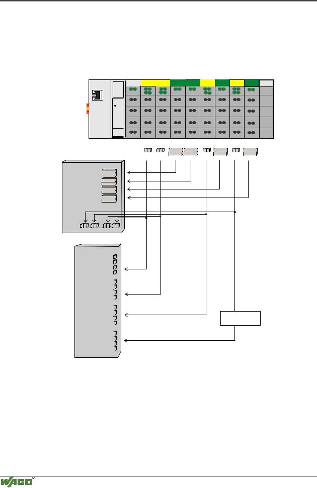
3.1.4.2Example of a process output image
The following example for the process output image comprises of 2 digital and 4 analog outputs.
It comprises of 4 words for the analog and 1 word for the digital outputs, , i.e. 5 words in total.
In addition, the output data can be read back by means of an offset of 200hex (0x0200) added to the MODBUS address.
Ethernet
 ON
ON
 LINK
LINK
 TxD/RxD
 ERROR
ERROR
 I/O
I/O
SY STEM |
|
W AGO I/O |
750-342 |
DO AO AO
Output modules
Process output image (Word)
MODBUS addresses
0x0000 / 0x0200 Word1
0x0001 / 0x0201 Word2
0x0002 / 0x0202 Word1
0x0003 / 0x0203 Word2
0x0004 / |
|
|
0x0204 |
Highbyte |
Lowbyte |
|
Process input image (Word)
750 - 501 550 550
Bit 1
Word1 Word1
Word1
Bit 2 Word2 Word2
MODBUS addresses
0x0200 |
Word1 |
|
Word2 |
||
0x0201 |
||
|
0x0202 |
Word1 |
0x0203 |
Word2 |
0x0204 |
|
Highbyte |
Lowbyte |
Process output image (Bit)
MODBUS addresses
0x0000 / 0x0200
0x0001 / 0x0201
Process input image (Bit)
MODBUS addresses
0x0200
0x0201
DO: Digital Output
AO: Analog Output
Fig. 3-8: Example of a process output image |
G012915e |
Modular I/O System
ETHERNET TCP/IP

26 • Fieldbus coupler 750-342
Data exchange
3.1.4.3Process data architecture for MODBUS/TCP
For some bus modules or their variations the process data architecture is specific for the fieldbus coupler used.
In the case of the ETHERNET coupler with MODBUS/TCP, the control/status byte is always masked in addition to the data bytes. This is required for the two-directional data exchange of the bus module with the higher-ranking control system. The control byte is transmitted from the control system to the module and the status byte from the module to the control system. This allows, for example, the display of overshooting or undershooting of the area.
Attention
Please refer to the respective bus module description in Chapter 4 "I/O modules" for the specific architecture of the control/status byte.
The following shows the representation of some selected modules in the process image.
In the examples, the order in which the modules are physically arranged in the node reflects the order in the image table starting with register address 0x0000. If the module is at any other position in the fieldbus node, the process data of all previous byte-wise oriented modules has to be taken into account, resulting in a basic register address for the module in the process image. The mentioned offset will be added to this basic address for addressing its process data words.
If an analog input or output module is added, it takes up 2 x 16 Bit input of output data. Therefore the first available digital point would be at word 2 keeping in mind that all process image addressing starts at WORD 0.
With the ETHERNET fieldbus coupler with MODBUS/TCP TCP, the process image is word aligned (word-alignment) and the control/status byte is always a low byte.
Modular I/O System
ETHERNET TCP/IP