Материал: m012900e
12 • The WAGO-I/O-SYSTEM 750 Power supply
2.4.1System supply voltage
The system supply voltage (24 V DC) is filtered with a voltage regulator before powering the coupler electronics as well as to the internal bus. Electrical isolation from the external fieldbus system depends on the type of Coupler/Controller.
The internal bus includes the internal communication between the coupler/controller and the bus modules as well as the power supply for the bus modules. The power supply is limited to a maximum value. This value depends on the type of Coupler/Controller. If the sum of the internal power consumption of all bus modules exceeds this value, it is necessary to add additional internal system supply modules (Order-No. 750-613).
The control electronics in the bus modules are powered by snap-fit mounting the bus modules using the internal bus contacts. A reliable contact is assured by the gold plated, self cleaning slide contacts. The removal of a bus module will cause an interruption in communication to the following bus modules.
The coupler/controller identifies the interruption point and displays a corresponding fault message.
Warning
Removing or inserting the I/O modules with the voltage applied can lead to undefined conditions. For this reason only remove the I/O modules when isolated from the power supply!
Modular I/O System
ETHERNET TCP/IP
The WAGO-I/O-SYSTEM 750 • 13
Power supply
2.4.2Supply Voltage Field Side
The voltage is automatically supplied when the I/O modules are snapped together. Self-cleaning power jumper contacts (P.J.C.s) ensure safe connections. The current capacity of the power contacts is 10 A max.
The PE contact is a preceding ground (earth) contact corresponding to the standards which can be used as a protective earth. The contact has a leakage capacity of 125 A.
Warning
Produce a low impedance connection from the carrier rail to the PE contact point in the cabinet.
Attention
Depending on the I/O function, some modules do not have P.J.C.s. It is important to note this when assembling a node. Many modules require field side power, many do not. Please review the circuit diagrams of the individual modules. An additional power supply module may be necessary.
Refer to the individual terminal/module data sheets!
When adding a power supply module, the field supply is always interrupted at the power contacts. From this point a new power supply is made, which can also include a potential change. This feature guarantees a high degree of system flexibility.
Modular I/O System
ETHERNET TCP/IP
14 • The WAGO-I/O-SYSTEM 750
Manufacturing Number
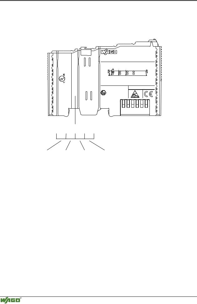
2.5 Manufacturing Number
The production number is part of the lateral marking on the component. The number contains the production date, the software version and the hardware of the component.
24V DC AWG 28-14 55°C max ambient
CL I DIV 2 Grp. A B C D op temp code T4A
LISTED 22ZA AND 22XM
-02----03 |
4246 |
1- |
2 |
090 |
|
|
ITEM-NO.:750-400 |
Hansastr. 27 |
2DI 24V DC 3.0ms |
|
|
D-32423 Minden |
0.08-2.5mm2 |
0V 24V DI1
Di2
PATENTS PENDING
II 3 G
KEMA 01ATEX1024 X EEx nA II T4
Manufacturing Number |
|
|||
|
0 9 0 |
1 - - 0 |
2 |
|
Calendar |
Year |
Software |
Hardware |
|
week |
|
version |
version |
|
Fig. 2-11: |
Manufacturing Number |
g01xx09e |
||
The remaining digits and characters represent internal information for WAGO Kontakttechnik GmbH.
As of calendar week 43/2000, the production number is also printed on the cover of the configuration and programming interface of the fieldbus coupler or controller.
Modular I/O System
ETHERNET TCP/IP
The WAGO-I/O-SYSTEM 750 • 15
Technical Data
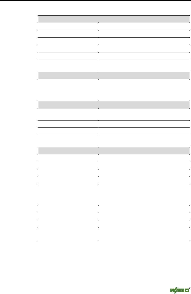
2.6 Technical Data
Mechanic
Material
Installation
modular by
Mounting position
Length of entire node
Marking
Wire range
Wire range
Contacts
Power jumpers contacts
Polycarbonate, Polyamide 6.6
on DIN 35 with interlock
double featherkey-dovetail
any position
≤ 831 mm
marking label type 247 and 248 paper marking label 8 x 47 mm
CAGE CLAMP® Connection 0,08 mm² ... 2,5 mm²
AWG 28-14
8 – 9 mm Stripped length
blade/spring contact self-cleaning
Current via power contactsmax
Voltage drop at Imax
Data contacts
10 A
< 1 V/64 modules
slide contact, hard gold plated 1,5µ, self-cleaning
Environmental conditions
Operating temperature |
0 °C ... 55 °C |
|
|
Storage temperature |
-20 °C ... +85 °C |
|
|
Relative humidity |
95 % without condensation |
|
|
Resistance to harmful substances |
acc. to IEC 60068-2-42 and IEC 60068-2-43 |
|
|
Special conditions |
Ensure that additional measures for components are |
|
taken, which are used in an environment involving: |
|
– dust, caustic vapors or gases |
|
– ionizing radiation. |
|
|
Mechanical strenght |
|
|
|
Vibration resistance |
acc. to IEC 60068-2-6 |
|
|
Shock resistance |
acc. to IEC 60068-2-27 |
|
|
Free fall |
acc. to IEC 60068-2-32 |
|
≤ 1m (module in original packing) |
|
|
Modular I/O System
ETHERNET TCP/IP
16 • The WAGO-I/O-SYSTEM 750
Technical Data
Safe electrical isolation
Air and creepage distance
Degree of protection
acc. to IEC 60646-1
|
Degree of protection |
|
|
IP 20 |
|
|
|
|
|
|
|
|
|
|
|
|
|
|
|
|
Electromagnetic compatibility* |
|
|
|
|
|
|||
|
|
|
|
|
|
|
|
|
|
|
Directive |
|
Test values |
|
Strength |
|
Evaluation |
|
|
|
|
|
|
|
|
class |
|
criteria |
|
|
|
|
|
|
|
||||
|
|
|
|
|
|
|
|
|
|
|
Immunity to interference acc. to EN 50082-2 (95) |
|
|
|
|
|
|||
|
|
|
|
|
|
|
|
||
|
EN 61000-4-2 |
|
4kV/8kV |
|
(2/4) |
|
B |
|
|
|
|
|
|
|
|
|
|
|
|
|
EN 61000-4-3 |
|
10V/m 80% AM |
|
(3) |
|
A |
|
|
|
|
|
|
|
|
|
|
|
|
|
EN 61000-4-4 |
|
2kV |
|
(3/4) |
|
B |
|
|
|
|
|
|
|
|
|
|
|
|
|
EN 61000-4-6 |
|
10V/m 80% AM |
|
(3) |
|
A |
|
|
|
|
|
|
|
|
|
|
|
|
|
Emmission to interference acc. to |
|
Measuring |
|
Class |
|
|||
|
EN 50081-2 (94) |
|
|
|
|
distance |
|
|
|
|
|
|
|
|
|
|
|
||
|
EN 55011 |
|
G% 9 P |
|
(30m) |
|
A |
|
|
|
|
|
G% 9 P |
|
|
|
|
|
|
* Exception: 750-630, 750-631 |
|
|
|
||
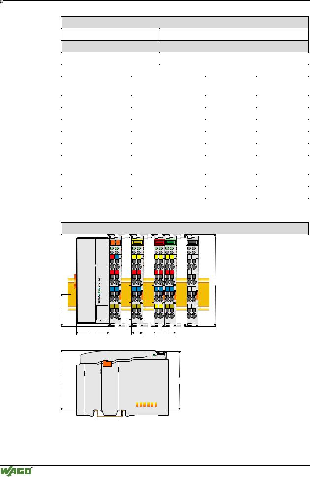
Dimensions |
|
|
|
|
|
01 |
02 |
|
|
|
|
A |
|
A |
A |
A |
A |
|
C |
C |
C |
C |
C |
B |
|
B |
B |
B |
B |
|
D |
D |
D |
D |
D |
24V 0V |
|
|
|
|
|
+ |
+ |
|
|
|
|
|
|
|
|
|
100 |
- |
- |
|
|
|
|
PE |
PE |
|
|
|
|
35 |
|
|
|
|
|
51 |
|
12 |
24 |
|
|
65 |
64 |
|
|
|
|
|
|
Fig. 2-12: Dimensions |
g01xx05d |
Modular I/O System
ETHERNET TCP/IP