Материал: m012900e
32 • Fieldbus coupler 750-342
Data exchange
3.1.5.1Memory areas
|
fieldbus coupler |
|
|
|
memory area |
|
|
|
for input data |
I/O modules |
|
|
word 0 |
||
|
|
|
|
|
1 |
|
|
|
input |
|
|
|
modules |
|
|
fieldbus |
|
|
|
master |
word 255 |
|
|
|
memory area |
|
|
|
for output data |
|
|
|
word 0 |
|
|
|
2 |
|
|
|
output |
|
|
|
modules |
|
|
|
|
I |
O |
word 255
Fig. 3-9: Memory areas and data exchange for a fieldbus coupler |
g012939e |
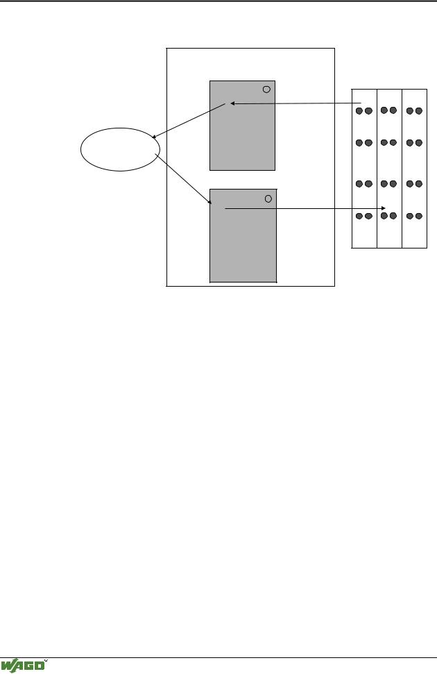
The coupler process image contains the physical data of the bus modules in a storage area for input data and in a storage area for output data (word 0 ... 255 each).
(1)The input module data can be read from the fieldbus side.
(2)In the same manner, writing on the output modules is possible from the fieldbus side.
In addition, all output data of the ETHERNET TCP/IP coupler are mirror imaged on a storage area with the address offset 0x0200. This allows to read output values back by adding 0x0200 to the MODBUS address.
3.1.5.2Addressing
3.1.5.2.1 Addressing the I/O modules
The arrangement of the I/O modules in a node is optional.
When addressing, first of all the more complex modules (modules occupying 1 or more bytes) are taken into account in accordance with their physical order behind the fieldbus coupler. As such, they occupy the addresses starting with word 0.
Following this, the data of the other modules (modules occupying less than 1 byte) follow, grouped into bytes. In accordance with the physical byte-wise order this data is used to fill up the bytes. As soon as a full byte is occupied by the bit-oriented modules, the next byte is automatically started.
Modular I/O System
ETHERNET TCP/IP
Fieldbus coupler 750-342 • 33
Data exchange
Note
For the number of input and output bits and/or bytes of the individual activated bus modules, please refer to the pertaining descriptions of the bus modules.
Note
Once a node is modified, a new architecture of the process image can result. As such, the address of the process data will alsochange. In the event of adding modules, the process data of all previous modules has to be taken into account.
Data width • :RUG FKDQQHO
Analog input modules
Analog output modules
Input modules for thermal elements
Input modules for resistance sensors
Pulse width output modules
Interface module
Up/down counter
I/O modules for angle and path measurement
Data width = 1 Bit / channel
Digital input modules
Digital output modules
Digital output modules with diagnosis (2 Bit / channel)
Power supply modules with fuse holder / diagnosis
Solid State power relay
Relay output modules
Table 3.1: I/O module data width
3.1.5.2.2 Address range
Address range for I/O module data:
Datawidth Address
Bit
Byte
Word
0.0 |
...0.8 |
...1.0 |
...1.8 |
..... |
...254.0 |
...254.8 |
...255.0 |
...255.8 |
... |
0.15 |
1.7 |
1.15 |
|
254.7 |
254.15 |
255.7 |
255.15 |
0 |
1 |
2 |
3 |
..... |
508 |
509 |
510 |
511 |
|
|
|
|
|
|
|
|
|
0 |
|
1 |
|
..... |
254 |
|
255 |
|
|
|
|
|
|
|
|
|
|
Table 3.2: Address range for the I/O module data
The register functions are to be found as from 0x1000 and can be addressed along with the implemented MODBUS function codes (read/write).
Modular I/O System
ETHERNET TCP/IP
34 • Fieldbus coupler 750-342
Data exchange
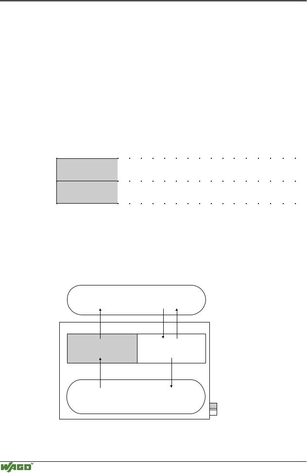
3.1.5.3Data exchange between MODBUS master and I/O modules
The data exchange between the MODBUS master and the I/O modules is made by the implemented MODBUS functions in the coupler with reading and writing in bits or bytes.
The controller handles four different types of process data:
•Input words
•Output words
•Input bits
•Output bits
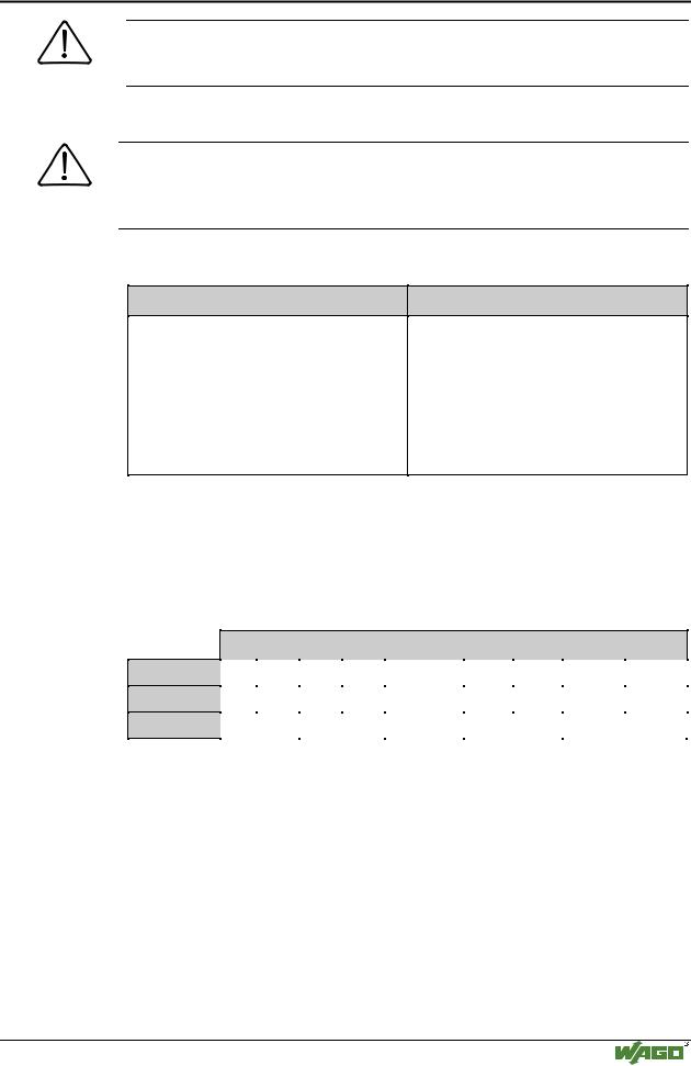
The word for word access to the digital input and output modules is made in accordance with the following table:
Digital inputs/ outputs
Process data
word
16. |
15. |
14. |
13. |
12. |
11. |
10. |
9. |
8. |
7. |
6. |
5. |
4. |
3. |
2. |
1. |
|
|
|
|
|
|
|
|
|
|
|
|
|
|
|
|
Bit |
Bit |
Bit |
Bit |
Bit |
Bit |
Bit |
Bit |
Bit |
Bit |
Bit |
Bit |
Bit |
Bit |
Bit |
Bit |
15 |
14 |
13 |
12 |
11 |
10 |
9 |
8 |
7 |
6 |
5 |
4 |
3 |
2 |
1 |
0 |
|
|
|
|
|
|
|
|
|
|
|
|
|
|
|
|
Table 3.3: Allocation of digital inputs/outputs to process data word acc. Intel format
The outputs can be read back by adding 0x0200 to the MODBUS address.
The register functions made available in the coupler, can be addressed by the MODBUS master along with the implemented MODBUS function codes (read/write). To this effect, the individual register address is entered in place of the address of a module channel.
MODBUS master |
||
0x000 |
0x000 |
|
|
(0x200) |
|
PII |
PIO |
|
0x0FF |
0x0FF |
|
(0x2FF) |
||
|
||
Inputs |
Outputs |
|
|
I/O modules |
|
|
PII = Process Input |
|
|
Image |
|
|
PIO = Process Output |
|
|
Image |
|
Fieldbus Coupler
Fig. 3-10: Data exchange between the MODBUS master and I/O modules |
g012927e |
Modular I/O System
ETHERNET TCP/IP

Fieldbus coupler 750-342 • 35
Starting up ETHERNET TCP/IP fieldbus nodes
3.1.6Starting up ETHERNET TCP/IP fieldbus nodes
This chapter shows the step-by-step procedure for starting up a
WAGO ETHERNET TCP/IP fieldbus node. The following also contains a description of how to read out the coupler-internal HTML pages.
Attention
This description is given as an example and is limited to the execution of a local startup of an individual ETHERNET fieldbus node with a computer running under windows which is not connected to a network.
Direct Internet connection should only be performed by an authorized network administrator and is, therefore, not described in this manual.
The procedure contains the following steps:
1.Noting the MAC-ID and establishing the fieldbus node
2.Connecting the PC and fieldbus node
3.Determining the IP address
4.Allocation of the IP address to the fieldbus node
5.Function of the fieldbus tests
6.Reading out information as HTML pages
3.1.6.1Note the MAC-ID and establish the fieldbus node
Before establishing your fieldbus node, please note the hardware address (MAC-ID) of your ETHERNET fieldbus coupler.
This is located on the rear of the fieldbus coupler and on the self-adhesive tearoff label on the side of the fieldbus coupler.
MAC-ID of the fieldbus coupler will be in this format:
---------- ----- ----- ----- -----.
3.1.6.2Connecting PC and fieldbus node
Connect the assembled ETHERNET TCP/IP fieldbus node via a hub or directly to the PC using a 10Base-T cable.
Attention
For a direct connection, a crossover cable is required instead of a parallel cable.
Now start the PC, functioning as master and BootP server, and switch on the voltage supply on the fieldbus coupler (DC 24 V power pack). Once the operating voltage has been switched on, the initialization starts. The fieldbus coupler determines the configuration of the bus modules and creates the process image.
During the startup the ’I/O’LED (Red) flashes at high frequency.
When the ’I/O’LED and the ’ON’LED light up green, the fieldbus coupler is ready for operation.
If an error has occurred during startup, it is indicated as an error code by the ’I/O’-LED flashing (red).
Modular I/O System
ETHERNET TCP/IP

36 • Fieldbus coupler 750-342
Starting up ETHERNET TCP/IP fieldbus nodes
3.1.6.3Determining IP addresses
If your PC is already connected to an ETHERNET network, it is very easy to determine the IP address of your PC. To do this, proceed as follows:
1.Go to the Start menu on your screen, menu item Settings and click on Control Panel.
2.Double click the icon Network.  The network dialog window will open.
3.- Under Windows NT: Select the register: Protocols and mark
the entry TCP/IP protocol.
- Under Windows 9x: Select the register: Configuration and mark the entry TCP/IP network card.
Attention
If the entry is missing, please install the respective TCP/IP component and restart your PC. The Windows-NT installation CD, or the installations CD for Windows 9x is required for the installation.
4.Subsequently, click the button "Properties...".
The IP address and the subnet mask are found in the ‘IP address’ tab.If applicable, the gateway address of your PC is found in the ‘Gateway’ tab.
5.Please write down the values:
IP address PC: |
----- . ----- |
. ----- |
. ----- |
Subnet mask: |
----- . ----- |
. ----- |
. ----- |
Gateway: |
----- . ----- |
. ----- |
. ----- |
6. Now select a desired IP address for your fieldbus node.
Attention
When selecting your IP address, ensure that it is in the same local network in which your PC is located.
7. Please note the IP address you have chosen:
IP address fieldbus node: |
----- . ----- |
. ----- |
. ----- |
3.1.6.4Allocating the IP address to the fieldbus node
The following describes how to allocate the IP address for the fieldbus node using the WAGO BootP server by way of an example. You can download a free copy from WAGO over the Internet under: http://www.wago.com/wagoweb/usa/eng/support/downloads/index.htm.
Modular I/O System
ETHERNET TCP/IP