Материал: m012900e
42 • Fieldbus coupler 750-342
LED Display
3.1.7.2Fieldbus status
The operating status of the communication via ETHERNET is signalled by means of the top LED group (ON, LINK, TxD/RxD and ERROR).
LED |
Meaning |
Trouble shooting |
|
|
|
ON |
|
|
|
|
|
green |
Fieldbus initialization is correct |
|
OFF |
Fieldbus initialization is not correct, |
Check the supply voltage (24V and 0V), |
|
no function or self-test |
check the IP configuration |
LINK |
|
|
|
|
|
green |
Link to a physical network exists |
|
OFF |
No link to a physical network |
Check the fieldbus connection. |
TxD/RxD |
|
|
|
|
|
green |
Data exchange taking place |
|
OFF |
No data exchange |
|
ERROR |
|
|
|
|
|
red |
Error on the fieldbus |
|
OFF |
No error on the fieldbus, normal operation |
|
3.1.7.3Node status
The operating status of the communication via the internal bus is signalled via the bottom I/O LED.
LED |
Meaning |
Trouble shooting |
|
|
|
I/O |
|
|
|
|
|
Green |
Fieldbus coupler operating perfectly |
|
Red |
a) During startup of fieldbus coupler: |
|
|
Internal bus being initialized, |
|
|
Startup displayed by LED flashing fast for approx. |
|
|
1-2 seconds |
|
Red |
b) After startup of fieldbus coupler: |
|
|
Errors, which occur, are indicated by three conse- |
Evaluate the fault message (fault code and |
|
cutive flashing sequences. There is a short pause |
fault argument). |
|
between each sequential flash. |
|
The coupler starts up after switching on the supply voltage. The "I/O" LED blinks. The "I/O" LED has a steady light following a fault free run-up.
In the case of a fault the "I/O" LED continues blinking. The fault is cyclically displayed by the blink code.
Modular I/O System
ETHERNET TCP/IP
Fieldbus coupler 750-342 • 43
LED Display
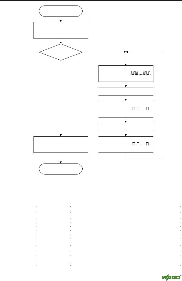
Switching on the power supply
Coupler/Controller starts up
“I/O”-LED is blinking
No
Test o.k.?
Yes
“I/O”-LED is shining
ready for operation
“I/O” LED
1st flash sequence
(Introduction of the error indication)
1st break
“I/O” LED
2nd flash sequence
Error code
(Number of flash cycles)
2nd break
“I/O” LED
3rd flash sequence
Error argument
(Number of flash cycles)
Fig. 3-16: Signalling of the LED for indication of the node status |
g012911e |
After clearing a fault, restart the coupler by cycling the power.
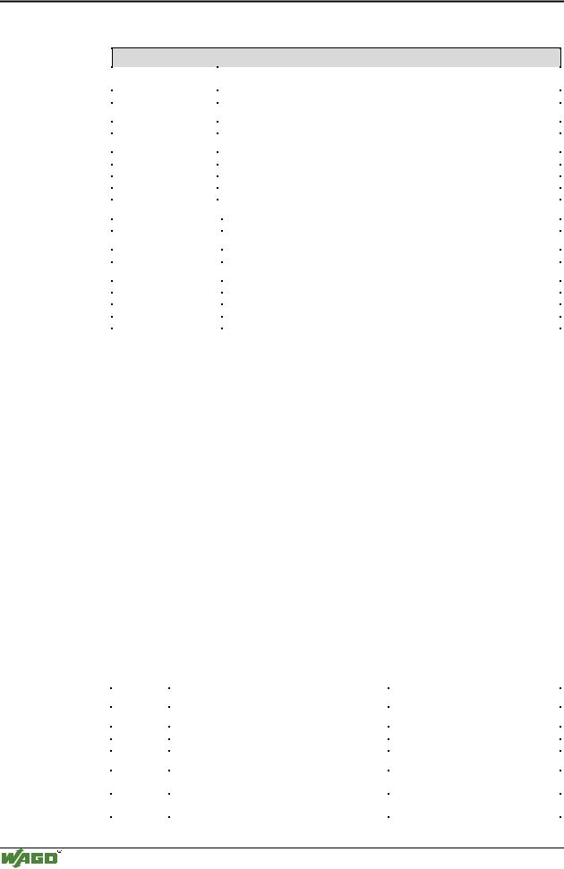
3.1.7.4Fault message via blink code from the I/O-LED
Fault argument |
Fault description |
|
|
Fault code 1: Hardware and Configuration fault |
|
|
|
0 |
EEPROM check sum fault / check sum fault in the parameter area of the flash memory |
1 |
Overflow of the internal buffer memory for the inline code |
2 |
Unknown data type |
3 |
Module type of the flash program memory could not be determined / is incorrect |
4 |
Fault when writing in the FLASH memory |
5 |
Fault when deleting the FLASH memory |
6 |
Changed I/O module configuration determined after AUTORESET |
Fault code 2: Fault in programmed configuration |
|
|
|
0 |
Incorrect table entry |
Fault code 3: Internal bus command fault |
|
|
|
0 |
No error argument is put out. |
Modular I/O System
ETHERNET TCP/IP
44 • Fieldbus coupler 750-342 LED Display
Fault code 4: Internal bus data fault
0 |
Data fault on internal bus or |
|
|
Internal bus interruption on coupler |
|
n* (n>0) |
Internal bus interrupted after I/O module n |
|
Fault code 5: Fault during register communication |
||
|
|
|
n* |
Internal bus fault during register communication after I/O module n |
|
Fault code 6: Fieldbus specific error |
||
|
|
|
1 |
No reply from the BootP server |
|
2 |
ETHERNET controller not recognized |
|
3 |
Invalid MACID |
|
4 |
TCP/IP initialization error |
|
Fault code 7: I/O module is not supported |
||
|
|
|
n* |
|
I/O module at position n is not supported |
Fault code 8: not used |
|
|
|
|
|
0 |
|
Fault code 8 is not used. |
Fault code 9: CPU-TRAP error |
||
|
|
|
1 |
|
Illegal Opcode |
2 |
|
Stack overflow |
3 |
|
Stack underflow |
4 |
|
NMI |
* The number of blink pulses (n) indicates the position of the I/O module. I/O modules without data are not counted (i.e. supply modules without diagnostics).
Example for a fault message
Fault: The 13th I/O module has been removed.
1.The "I/O" LED starts the fault display with the first blink sequence (approx. 10 Hz).
2.The second blink phase (approx. 1 Hz) follows the first pause. The "I/O" LED blinks four times and thus signals the fault code 4 (internal bus data fault).
3.The third blink sequence follows the second pause. The "I/O ERR" LED
blinks twelve times. The fault argument 12 means that the internal bus is interrupted after the 12th I/O module. Supply voltage status
There are two green LED’s in the coupler supply section to display the supply voltage. The left LED (A) indicates the 24 V supply for the coupler. The right hand LED (C) signals the supply to the field side, i.e. the power jumper contacts.
LED |
Meaning |
Trouble shooting |
|
|
|
A |
|
|
|
|
|
green |
Operating voltage for the system exists. |
|
OFF |
No operating voltage for the system. |
Check the supply voltage (24V and 0V). |
C |
|
|
|
|
|
green |
Operating voltage for the power jumper contacts |
|
|
exists. |
|
OFF |
No operating voltage for the the power jumper con- |
Check the supply voltage (24V and 0V). |
|
tacts. |
|
Modular I/O System
ETHERNET TCP/IP

Fieldbus coupler 750-342 • 45
Fault behavior
3.1.8Fault behavior
3.1.8.1Fieldbus failure
A field bus failure is given i. e. when the master cuts-out or the bus cable is interrupted. A fault in the master can also lead to a fieldbus failure.
A field bus failure is indicated when the red "ERROR"-LED is illuminated.
If the watchdog is activated, the fieldbus coupler firmware evaluates the watchdog-register in the case of fault free communication, and the coupler answers all following MODBUS TCP/IP requests with the exception code 0x0004 (Slave Device Failure).
More information
i For detailed information on the Watchdog register see Chaper 6.2.12 "Watchdog (Fieldbus failure)".
3.1.8.2Internal bus fault
An internal bus fault is created, for example, if an I/O module is removed. If this fault occurs during operation the output modules behave in the same manner as an I/O module stop. The "I/O" LED blinks red.
The coupler generates a fault message (fault code and fault argument). After clearing the internal bus fault, restart the coupler by cycling the power.
The coupler starts up. The transfer of the process data is then resumed and the node outputs are correspondingly set.
Modular I/O System
ETHERNET TCP/IP
46 • Fieldbus coupler 750-342
Technical Data
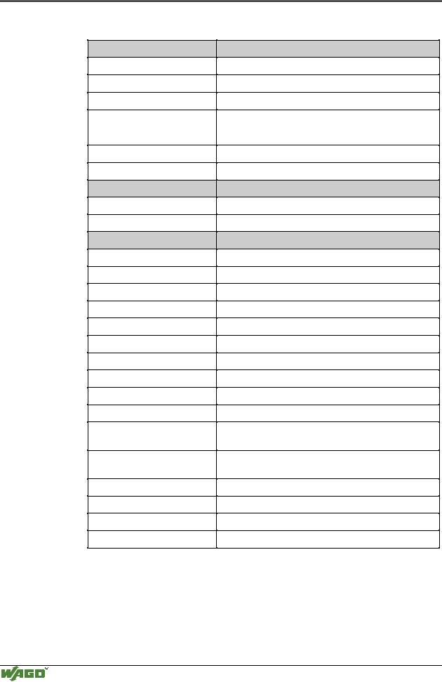
3.1.9Technical Data
System data
Max. n. of nodes
Transmission medium
Buscoupler connection
Max. length of fieldbus segment
Baud rate
Protocols
Approvals
UL
Conformity marking
Technical Data
limited by ETHERNET specification
Twisted Pair S-UTP 100 Ω cat. 5
RJ45
100 m between hub station and 750-342;
max. length of network limited by ETHERNET specification
10 Mbit/s
MODBUS/TCP, HTTP, BootP
E175199, UL508
Œ
Max. n. of I/O modules
Input process image
Output process image
max. n. of socket connections
Voltage supply
Input currentmax
Efficiency of the power supply
Internal current consumption
Total current for I/O modules
Isolation
Voltage via power jumper contactsmax
Current via power jumper contactsmax
Dimensions (mm) B x H x T
Weight
EMC Immunity to interference
EMC Emission of interference
64
max. 512 Byte
max. 512 Byte
1 HTTP, 3 MODBUS/TCP
DC 24 V (-15 % / + 20 %)
500 mA at 24 V
87 %
200 mA at 5 V
1800 mA at 5 V
500 V system/supply
DC 24 V (-15 % / + 20 %)
DC 10 A
51 x 65* x 100 (*from upper edge of DIN 35 rail)
approx. 195 g
acc. to EN 50082-2 (95)
acc. to EN 50081-2 (94)
Modular I/O System
ETHERNET TCP/IP