Материал: m012900e
Fieldbus coupler 750-342 • 27
Data exchange
3.1.4.3.1 750-404, /000-00X Counter modules
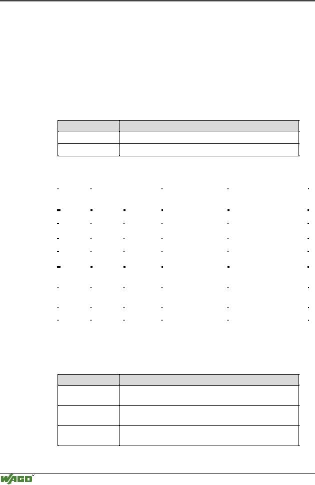
This process data architecture holds true for the counter modules 750-404, 750-404/000-001, 750-404/000-002 and 750–404/000-004.
Item-No.: Description:
750-404
750-404/000-001
750-404/000-002
750-404/000-004
Up/Down Counter
2 Channel Up Counter with enable input
Peak Time Counter
Up/Down Counter (switching outputs)
The data format of the counter modules five bytes is mapped out by the module as four data bytes and one additional control/status byte. The module supplies a 32 bit counter-output. Three words each in the process image are occupied with word-alignment.
|
Address |
Bytes |
|
|
|
Comment |
|
Module |
|
Offset |
High |
|
Low |
|
|
|
|
|
|
|
|
|
|
|||
|
|
|
|
|
|
|
|
|
|
0 |
|
|
C/S |
|
Control-/ Status byte |
|
Module 1: |
|
|
|
|
|
|
|
750-404, |
|
|
1 |
D1 |
|
D0 |
|
|
||
|
|
|
|
750-404/000-001, |
||||
|
|
|
|
|
|
Data bytes |
||
|
2 |
D3 |
|
D2 |
|
750-404/000-002, |
||
|
|
|
|
|
|
|
750-404/000-004 |
|
|
3 |
User data |
|
User data |
|
Data bytes |
|
Module 2: |
|
|
|
|
Analog module Channel 1 |
||||
|
|
|
|
|
|
|
|
|
|
4 |
User data |
|
User data |
|
Data bytes |
|
Module 2: |
|
|
|
|
Analog module Channel 2 |
||||
|
|
|
|
|
|
|
|
|
|
... |
... |
... |
... |
... |
|||
The input bytes D0 to D3 form the 32 bit counter-output.
In the output bytes D0 to D3, the initial value of the counter can be set.
3.1.4.3.2 750-404/000-005 2 Channel Up Counter 16 Bit
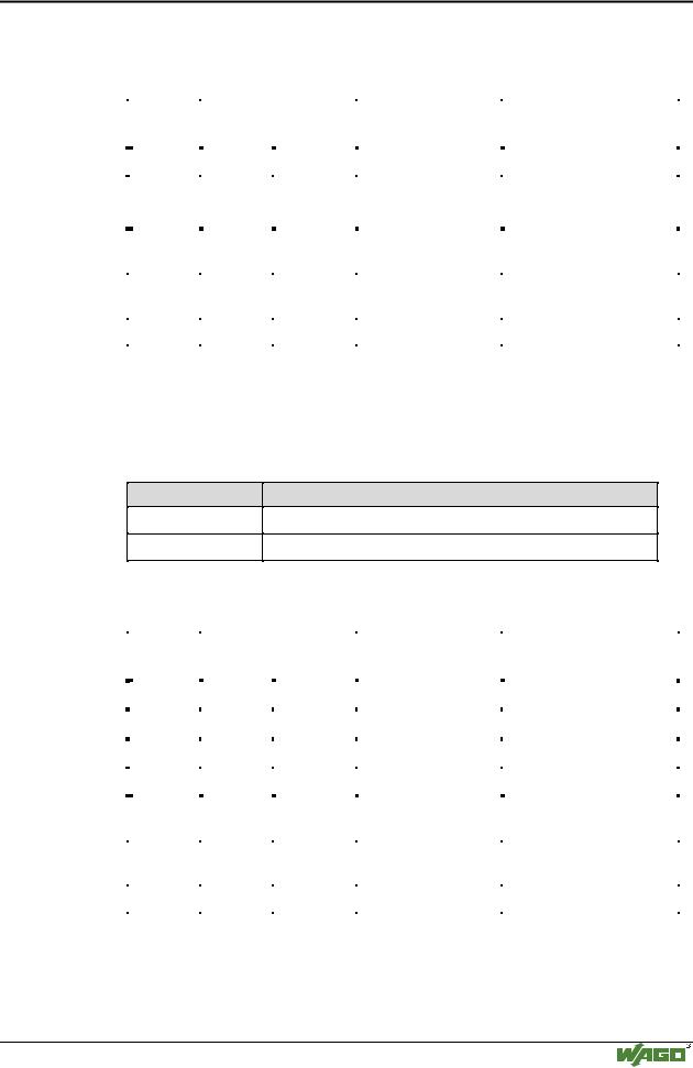
The data format of the counter modules five bytes is mapped out by the module as four data bytes and one additional control/status byte. Three words each in the process image are occupied with word-alignment .
|
Address |
Bytes |
|
|
|
Comment |
|
Module |
|
Offset |
High |
|
Low |
|
|
|
|
|
|
|
|
|
|
|||
|
|
|
|
|
|
|
|
|
|
0 |
|
|
C/S |
|
Control/ Statusbyte |
|
|
|
|
|
|
|
|
|
|
Module 1: |
|
1 |
D1 |
|
D0 |
|
Data bytes Counter 1 |
|
|
|
|
|
750-404/000-005 |
|||||
|
|
|
|
|
|
|
||
|
2 |
D3 |
|
D2 |
|
Data bytes Counter 2 |
|
|
|
|
|
|
|
|
|
|
|
|
3 |
User data |
|
User data |
|
Data bytes |
|
Module 2: |
|
|
|
|
Analog module Channel 1 |
||||
|
|
|
|
|
|
|
|
|
|
|
|
|
|
|
|
|
|
|
4 |
User data |
|
User data |
|
Data bytes |
|
Module 2: |
|
|
|
|
Analog module Channel 2 |
||||
|
|
|
|
|
|
|
|
|
|
|
|
|
|
|
|||
|
... |
... |
... |
... |
... |
|||
|
|
|
|
|
|
|
|
|
Modular I/O System
ETHERNET TCP/IP
28 • Fieldbus coupler 750-342
Data exchange
The input bytes D0 and D1 form the 16 bit reading of counter 1 and the input bytes D2 and D3 form the 16 bit reading of counter 2.
When setting the counter, the load value of counter 1 is transferred in the output bytes D0 and D1. The load value of counter 2 is transferred respectively in the output bytes D2 and D3.
3.1.4.3.3 750-511, /000-002 2-Channel Digital Pulsewidth module
This process data architecture holds true for the 2 Channel Pulsewidth modules 750-511 and 750–511/000-002.
Item-No.: Description:
750-511
750-511/000-002
2DO 24V DC 0.1A Pulsewidth
2DO 24V DC 0.1A Pulsewidth 100Hz
The process image of the 750-511 and 750-511/000-002 appears with 6 bytes of input and 6 bytes of output data. Four words in the process image are occupied with word-alignment .
|
Address |
Bytes |
|
|
|
Comment |
|
Module |
|
Offset |
High |
|
Low |
|
|
|
|
|
|
|
|
|
|
|||
|
|
|
|
|
|
|
|
|
|
0 |
|
|
C/S-0 |
|
Control / Status byte |
|
Module 1 Channel 1: |
|
|
|
|
|
|
|
750-511, |
|
|
1 |
D1-0 |
|
D0-0 |
|
Data bytes |
||
|
|
|
750-511/000-002 |
|||||
|
2 |
|
|
C/S-1 |
|
Control / Status byte |
|
Module 1 Channel 2: |
|
|
|
|
|
|
|
750-511, |
|
|
3 |
D1-1 |
|
D0-1 |
|
Data bytes |
||
|
|
|
750-511/000-002 |
|||||
|
|
|
|
|
|
|
||
|
4 |
User data |
|
User data |
|
Data bytes |
|
Module 2: |
|
|
|
|
Analog Module Channel 1 |
||||
|
|
|
|
|
|
|
|
|
|
|
|
|
|
|
|
|
|
|
5 |
User data |
|
User data |
|
Data bytes |
|
Module 2: |
|
|
|
|
Analog Module Channel 2 |
||||
|
|
|
|
|
|
|
|
|
|
|
|
|
|
|
|||
|
... |
... |
... |
... |
... |
|||
|
|
|
|
|
|
|
|
|
3.1.4.3.4 750-630, /000-00X SSI encoder interface 24 Bit
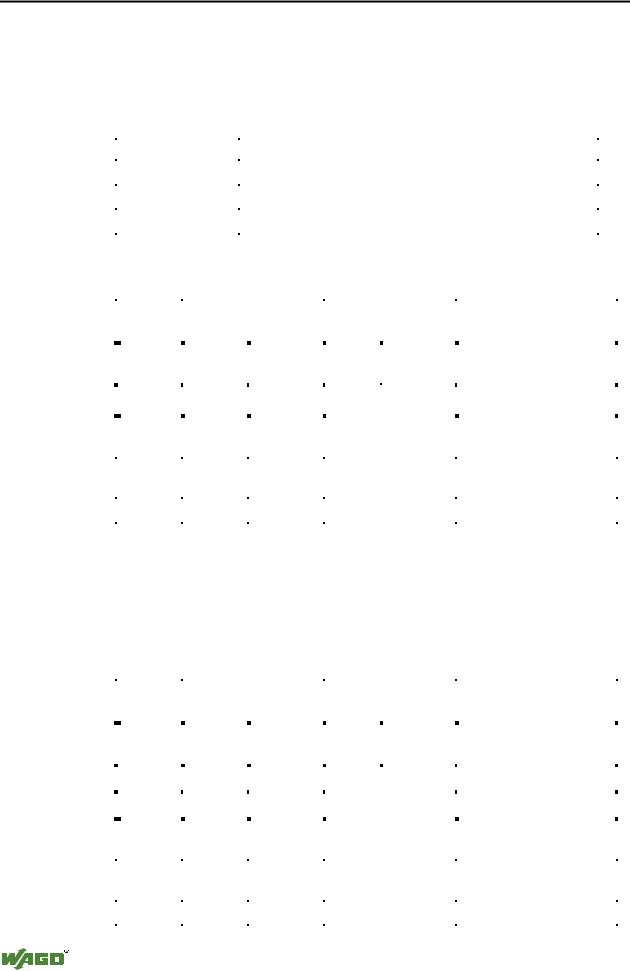
This process data architecture holds true for the SSI encoder interface modules 750-630, 750-630/000-001 and 750–630/000-006.
Item-No.:
750-630
750-630/000-001
750-630/000-006
Description:
SSI encoder interface 24Bit, 125kHz Gray code, alternative Data format
SSI encoder interface 24Bit, 125kHz Binary code, alternative Data format
SSI encoder interface 24Bit, 250kHz Gray code, alternative Data format
Modular I/O System
ETHERNET TCP/IP
Fieldbus coupler 750-342 • 29
Data exchange
The module is seen like an analog input with 2 x 16 Bit input data, i.e. with a total of 4 bytes user data. With word-alignment 2 words are used in the input area of the local process image.
|
Address |
|
Bytes |
|
|
|
Comment |
|
Module |
|
Offset |
|
High |
|
Low |
|
|
|
|
|
|
|
|
|
|
|
|||
|
|
|
|
|
|
|
|
|
|
|
0 |
|
D1 |
|
D0 |
|
|
|
Module 1: |
|
|
|
|
|
|
|
Data bytes |
750-630, |
|
|
1 |
|
D3 |
|
D2 |
|
|||
|
|
|
|
750-630/000-001, |
|||||
|
|
|
|
|
|
|
|
||
|
|
|
|
|
|
|
|
750-630/000-006 |
|
|
2 |
|
User data |
|
User data |
|
Data bytes |
|
Module 2: |
|
|
|
|
|
Analog module Channel 1 |
||||
|
|
|
|
|
|
|
|
|
|
|
|
|
|
|
|
|
|
|
|
|
3 |
|
User data |
|
User data |
|
Data bytes |
|
Module 2: |
|
|
|
|
|
Analog module Channel 2 |
||||
|
|
|
|
|
|
|
|
|
|
|
|
|
|
|
|
||||
|
... |
... |
... |
... |
... |
||||
|
|
|
|
|
|
|
|
|
|
3.1.4.3.5 750-631, /000-001 Incremental Encoder Interface
This process data architecture holds true for the Incremental Encoder Interface modules 750-631 and 750–631/000-001.
Item-No.: Description:
750-631
750-631/000-001
Incremental encoder interface, 4 times sampling
Incremental encoder interface, 1 times sampling
The bus module 750-631 and 750-631/000-001 002 appears with 6 bytes of input and 6 bytes of output data and occupying 4 words each with word-align- ment.
|
Address |
Bytes |
|
|
|
Comment |
|
Module |
|
|
Offset |
High |
|
Low |
|
|
|
|
|
|
|
|
|
|
|
|
|||
|
|
|
|
|
|
|
|
|
|
|
0 |
|
|
C/S |
|
Control / Status byte |
|
|
|
|
|
|
|
|
|
|
|
Module 1: |
|
|
1 |
D1 |
|
D0 |
|
ead/set counter word |
|
|
|
|
|
|
|
|
|||||
|
|
|
|
|
|
|
750-631, |
|
|
|
3 |
|
|
(D2)*) |
|
(period) |
|
||
|
|
|
|
750-631/000-001 |
|
||||
|
4 |
D4 |
|
D3 |
|
read latch word |
|
|
|
|
|
|
|
|
|
|
|
|
|
|
5 |
User data |
|
User data |
|
Data bytes |
|
Module 2: |
|
|
|
|
|
Analog module Channel 1 |
|
||||
|
|
|
|
|
|
|
|
|
|
|
|
|
|
|
|
|
|
|
|
|
6 |
User data |
|
User data |
|
Data bytes |
|
Module 2: |
|
|
|
|
|
Analog module Channel 2 |
|
||||
|
|
|
|
|
|
|
|
|
|
|
|
|
|
|
|
|
|||
|
... |
... |
... |
... |
... |
|
|||
|
|
|
|
|
|
|
|
|
|
In the low byte, the control/status byte is on offset 0.
The data word D0/D1 contains the counter word (read/set), whereas the data word D3/D4 contains the latch word (read).
*) In the operating mode of permanent period measurement, the period duration is in D2 together with D3/D4.
Modular I/O System
ETHERNET TCP/IP
30 • Fieldbus coupler 750-342
Data exchange
3.1.4.3.6750-650 RS232 Interface module,
750-651 TTY-,20 mA Current Loop,
750-653 RS485 Interface module
This process data architecture holds true for the modules 750-650, 750-651 and 750–653.
Item-No.: |
Description: |
|
|
750-650 |
RS 232 C Interface 9600,n,8,1 |
|
|
750-651 |
TTY Interface, 20 mA Current Loop |
|
|
750-653 |
RS485 Interface |
|
|
The modules appear on the bus as a combined analog input and output module with 3 x 16-bit input and output data, i.e. with a total of 4 bytes user data, occupying 2 words each with word-alignment.
|
Address |
|
Bytes |
|
|
|
Comment |
|
|
|
|
Module |
|
|
Offset |
|
High |
|
Low |
|
|
|
|
|
|
|
|
|
|
|
|
|
|
|
|
|
|
|
|||
|
|
|
|
|
|
|
|
|
|
|
|
|
|
|
0 |
|
D0 |
|
C/S |
|
Data |
|
Control / |
|
|
Module 1: |
|
|
|
|
|
byte |
|
Status byte |
|
750-650, |
|
||||
|
|
|
|
|
|
|
|
|
|
||||
|
|
|
|
|
|
|
|
|
|
|
750-651, |
|
|
|
1 |
|
D2 |
|
D1 |
|
Data bytes |
|
|
||||
|
|
|
|
|
|
||||||||
|
|
|
|
|
750-653 |
|
|||||||
|
2 |
|
User data |
|
User data |
|
Data bytes |
|
|
Module 2: |
|
||
|
|
|
|
|
|
Analog module Channel 1 |
|
||||||
|
|
|
|
|
|
|
|
|
|
|
|
|
|
|
|
|
|
|
|
|
|
|
|
|
|
|
|
|
3 |
|
User data |
|
User data |
|
Data bytes |
|
|
Module 2: |
|
||
|
|
|
|
|
|
Analog module Channel 2 |
|
||||||
|
|
|
|
|
|
|
|
|
|
|
|
|
|
|
|
|
|
|
|
|
|
|
|
||||
|
... |
... |
... |
|
|
... |
|
... |
|
||||
|
|
|
|
|
|
|
|
|
|
|
|
|
|
3.1.4.3.7 750-650/000-001 RS232 Interface module 5 Byte
The RS232 interface module 750-650 can also be operated with a data format of 5 bytes and one Control/Status byte, i.e. a total of 6 bytes user data. For this data format, order the variation with the part number 750-650/000-001, occupying 3 words each with word-alignment in the input and output area of the process image.
|
|
Address |
|
Bytes |
|
|
|
Comment |
|
|
|
Module |
|
|
|
Offset |
|
High |
|
Low |
|
|
|
|
|
|
|
|
|
|
|
|
|
|
|
|
|
|
|||
|
|
|
|
|
|
|
|
|
|
|
|
|
|
|
|
0 |
|
D0 |
|
C/S |
|
Data |
|
Control / |
|
|
|
|
|
|
|
|
byte |
|
Status byte |
|
|
|
|||
|
|
|
|
|
|
|
|
|
|
Module 1: |
|
||
|
|
|
|
|
|
|
|
|
|
|
|
|
|
|
|
|
|
|
|
|
|
|
|
|
|
|
|
|
|
1 |
|
D2 |
|
D1 |
|
Data bytes |
750-650/000-001 |
|
|||
|
|
|
|
|
|
|
|
|
|
|
|||
|
|
2 |
|
D4 |
|
D3 |
|
|
|
|
|||
|
|
|
|
|
|
|
|
||||||
|
|
|
|
|
|
|
|
|
|
|
|||
|
|
|
|
|
|
|
|
|
|
|
|
|
|
|
|
3 |
|
User data |
|
User data |
|
Data bytes |
|
Module 2: |
|
||
|
|
|
|
|
|
Analog module Channel 1 |
|
||||||
|
|
|
|
|
|
|
|
|
|
|
|
|
|
|
|
|
|
|
|
|
|
|
|
|
|
|
|
|
|
4 |
|
User data |
|
User data |
|
Data bytes |
|
Module 2: |
|
||
|
|
|
|
|
|
Analog module Channel 2 |
|
||||||
|
|
|
|
|
|
|
|
|
|
|
|
|
|
|
|
|
|
|
|
|
|
|
|
||||
|
|
... |
... |
... |
|
|
... |
... |
|
||||
|
|
|
|
|
|
|
|
|
|
|
|
|
|
|
|
|
|
|
|
|
|
|
|
|
|
|
|
Modular I/O System
ETHERNET TCP/IP

Fieldbus coupler 750-342 • 31
Data exchange
3.1.5Data exchange
Process data exchange with the ETHERNET TCP/IP fieldbus coupler occurs via the MODBUS/TCP protocol.
MODBUS/TCP works according to the master/slave principle. The master is a superimposed control unit, i.e. a PC or a PLC device. The ETHERNET TCP/IP couplers of the WAGO-I/O-SYSTEM are slave devices.
The master makes a query for communication. Through adressing, this query can be sent to a specific node. The nodes receive the query and return a response to the master, depending on the kind of query.
A coupler can communicate with a certain number of simultaneous connections (socket connections) to other network subscribers:
•1 connection for HTTP (reading HTML pages from coupler) and
•3 connections via MODBUS/TCP (reading or writing input and output data from coupler).
The maximum number of simultaneous connections cannot be exceeded. If further connections are to be made, terminate existing connections beforehand.
For a data exchange, the ETHERNET TCP/IP fieldbus coupler is equipped with two interfaces:
•the interface to fieldbus (-master) and
•the interface to the bus modules.
Data exchange takes place between MODBUS master and the bus modules. The master accesses the bus module data via implemented MODBUS functions.
Modular I/O System
ETHERNET TCP/IP