Материал: m012900e
Fieldbus controller 750-842 • 77
Starting up ETHERNET TCP/IP fieldbus nodes
The following describes how to allocate the IP address for the fieldbus node using the WAGO BootP server by way of an example. You can download a free copy from WAGO over the Internet under:
http://www.wago.com/wagoweb/usa/eng/support/downloads/index.htm.
Note
The IP address can be allocated under other operating systems (i.e. under Linux) as well as with any other BootP servers.
Attention
The IP address can be allocated in a direct connection via a crossover cable or via a parallel cable and a hub. An allocation over a switch is not possible.
BootP table
Note
Prerequisite for the following steps is the correct installation of the WAGO BootP server.
1.Go to the Start menu, menu item Programs / WAGO Software / WAGO BootP Server and click on WAGO BootP Server configuration. Or go to
Start menu, menu item Programs/WAGO Software/WAGO BootP Server and click on WAGO BootP Server then click on the Edit
Bootptab button located on the right hand side of the display.
An editable table will appear: "bootptab.txt".
This table displays the data base for the BootP server. Directly following the list of all notations used in the BootP table there are two examples for the allocation of an IP address.
"Example of entry with no gateway" and "Example of entry with gateway".
Fig. 3-31: BootP table |
p012908e |
Modular I/O System
ETHERNET TCP/IP
78 • Fieldbus controller 750-842
Starting up ETHERNET TCP/IP fieldbus nodes
The examples mentioned above contain the following information:
Declaration |
Meaning |
node1, |
Any name can be given for the node here. |
node2 |
|
ht=1 |
Specify the hardware type of the network here. |
|
The hardware type for ETHERNET is 1. |
|
(The numbers are described in RFC1700) |
ha=0030DE000100
ha=0030DE000200
ip= 10.1.254.100 ip= 10.1.254.200
T3=0A.01.FE.01
Specify the hardware address or the MAC-ID of the ETHERNET fieldbus controller (hexadecimal).
Enter the IP address of the ETHERNET fieldbus controller (decimal) here.
Specify the gateway IP address here.
Write the address in hexadecimal form.
sm=255.255.0.0 In addition enter the Subnet-mask of the subnet (decimal), where the ETHERNET fieldbus controller belongs to.
No gateway is required for the local network described in this example. Therefore, the first example: "Example of entry with no gateway" can be used.
2.Move the mouse pointer to the text line: "KeinProxy:ht=1:ha=0030DE000100:ip=10.1.254.100" and delete the 12 character hardware address which is entered after ha=...
Enter the MAC-ID of your own network controller.
3.If you want to give your fieldbus node a name, delete the name "node1" and enter any name in its place.
4.To assign the controller a desired IP address, delete the IP address specified in the example which is entered after ip=...
Replace it with the IP address you have selected, making sure you are separating the 3 digit numbers by a decimal.
5.Because the second example is not necessary at present, insert a “#” in front of the text line of the second example: "# hamburg:hat=1:ha=003 0DE 0002 00:ip=10.1.254.200:T3=0A.01.FE.01", so that this line will be ignored.
Note
To address more fieldbus nodes, enter a corresponding text line showing the corresponding entries for each node. Also note that the # symbol tells the BootP server to ignore any data after it, for that specific line.
6.Save the altered settings in this text file "bootptab.txt". To do this go to the File menu, menu item Save, and close the editor.
Modular I/O System
ETHERNET TCP/IP
Fieldbus controller 750-842 • 79
Starting up ETHERNET TCP/IP fieldbus nodes
BootP Server
7.Now open the dialog window for the WAGO BootP server by going to the Start menu on your screen surface, menu item Program /
WAGO Software / WAGO BootP Server and click on WAGO BootP
Server.
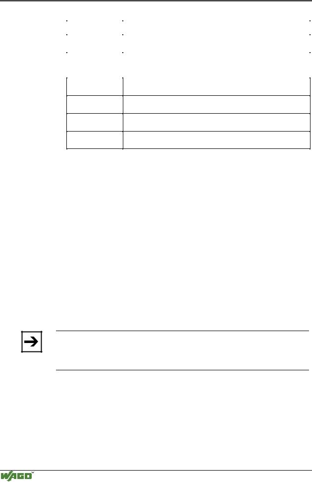
8.Click on the "Start" button in the opened dialog window.
This will activate the inquiry/response mechanism of the BootP protocol. A series of messages will be displayed in the BootP server. The error messages indicate that some services (e.g. port 67, port 68) in the operating system have not been defined. DO NOT BE ALARMED THIS IS THE CORRECT OPERATION FOR THIS EXAMPLE.
Fig. 3-32: Dialog window of the WAGO BootP server with messages |
P012909d |
9.Now it is important to restart the controller by resetting the hardware . This ensures that the new IP address will be accepted by the controller.
To do this, cycle power to the fieldbus controller for approximately 2 seconds or press the operating mode switch down which is located behind the configuration interface flap located on the front of the coupler.
Following this, you should see a reply from the buscoupler stating that the IP address has been accepted (no errors). The IP address is now permanently stored in the coupler and will be retained even following the removal of the coupler or a longer voltage failure. The only way the IP address can be changed is by using the BootP software again.
10.Subsequently, click on the "Stop" button and then on the "Exit" button, to close the BootP Server .
3.2.6.5Testing the function of the fieldbus node
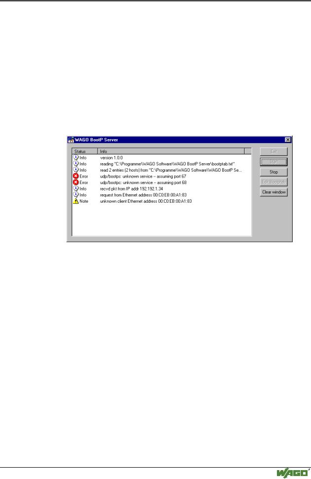
1.To test the communication with the coupler and the correct assignment of the IP address call up the DOS prompt under Start menu / Program / MSDOS Prompt.
2.Enter the command: "ping" with the IP address you have assigned in the following form:
ping [space] XXXX . XXXX . XXXX . XXXX (=IP address).
Modular I/O System
ETHERNET TCP/IP
80 • Fieldbus controller 750-842
Starting up ETHERNET TCP/IP fieldbus nodes
Example: ping 10.1.254.202
Fig. 3-33: Example for the function test of a fieldbus node |
P012910e |
3.When the Return key has been pressed, your PC will receive a response from the controller, which will then be displayed in the DOS prompt.
If the error message: "Timeout" appears instead, please compare your entries again to the allocated IP address and check all conections.
4.Also note that the TXD/RXD light will flash verifying each response
5.When the test has been performed successfully, you can close the DOS prompt. The network node has now been prepared for communication.
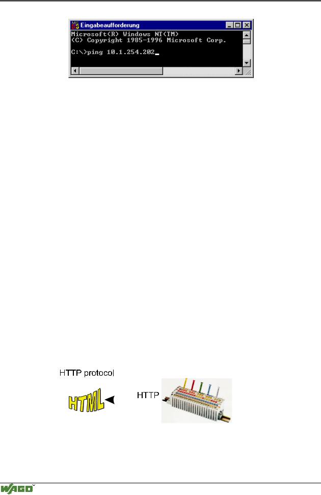
3.2.6.6Viewing the HTML pages
The information saved in the fieldbus controller can be viewed as an HTML page using a web browser.
•Information on the fieldbus node (Terminal Status):
-Number of digital, analog or complex modules and their model numbers
-Representation of the process image
•Information on the fieldbus controller (Controller and Network Details):
-Order number
-Firmware version
-MAC-ID
-IP address
-Gateway address (if applicable)
-Subnet mask
-Number of transmitted and received packets
•Diagnostic information on the fieldbus controller (Controller Status):
-Error code
-Error argument
-Error description
|
|
|
|
|
|
|
|
|
|
|
|
Fig. 3-34: Viewing the information through the HTTP protocol |
G012916d |
||||
Modular I/O System
ETHERNET TCP/IP

Fieldbus controller 750-842 • 81
Starting up ETHERNET TCP/IP fieldbus nodes
Please proceed as follows:
1.Open a web browser such as Microsoft Internet-Explorer, Netscape Navigator, ...
2.Simply enter the IP address of your fieldbus node in the address field of the browser and press the Enter key.
The first HTML page with the information on your fieldbus controller will be displayed in the browser window. Use the hyperlinks to find out more information.
Attention
If the pages are not displayed after local access to the fieldbus node, then define in your web browser that, as an exception, no proxyserver is to be used for the IP address of the node.
Modular I/O System
ETHERNET TCP/IP