Материал: m012900e
Fieldbus controller 750-842 • 87
LED Display
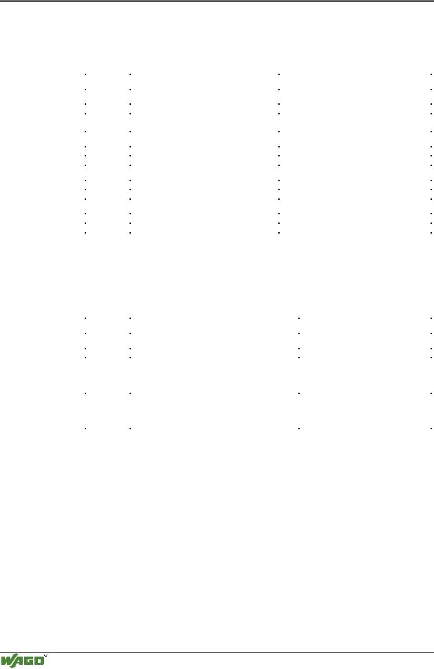
3.2.8LED Display
The controller possesses several LED’s for on site display of the controller operating status or the complete node.
ETHERNET |
01 |
02 |
status |
|
voltage supply |
|
|||
ON |
A |
|
|
|
|
-power jumper contacts |
|
||
|
|
C |
|
|
LINK |
B |
|
-system |
|
|
D |
|
||
|
|
|
|
|
TxD/RxD |
24V 0V |
|
|
|
ERROR |
|
|
|
|
I/O |
+ |
+ |
|
|
USR |
|
|
||
|
|
|
|
|
Fig. 3-35: Display elements 750-842 |
g012902e |
|||
A differentiation between two LED groups is made.
The first group = fieldbus contains the solid color LEDs having the designation ON (green), LINK (green), TxD/RxD (green) and ERROR (red) indicating the operating status of the communication via ETHERNET.
The second group = internal bus consists of the three-color I/O LED (red/green/orange). This LED is used to display the status of the internal bus, i. e. the status of the fieldbus node.
The three-color USR-LED can be accessed by a user program in the programmable fieldbus controller.
LEDs located on the right-hand side in the coupler power supply section show the status of the supply voltage.
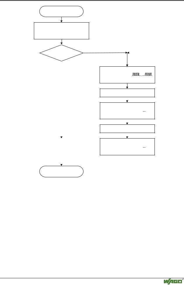
3.2.8.1Blink code
A blink code displays detailed fault messages. A fault is cyclically displayed using up to 3 different blink sequences.
•The first blink sequence (approx. 10 Hz) indicates the fault display.
•After a pause, a second blink sequence appears (approx. 1 Hz). The number of blink impulses gives the fault code.
•The third blink sequence (approx. 1 Hz) appears following a further pause. The number of blink pulses indicates the fault argument (where the faulty module is physically located on the node).
Modular I/O System
ETHERNET TCP/IP
88 • Fieldbus controller 750-842
LED Display
3.2.8.2Fieldbus status
The operating status of the communication via ETHERNET is signalled via the top LED group (ON, LINK, TxD/RxD and ERROR).
LED |
Meaning |
Trouble shooting |
|
|
|
ON |
|
|
|
|
|
green |
Fieldbus initialization is correct |
|
OFF |
Fieldbus initialization is not correct, |
Check the supply voltage (24V and 0V), |
|
no function or self test |
check the IP configuration |
LINK |
|
|
|
|
|
green |
Link to a physical network exists |
|
OFF |
No link to a physical network |
Check the fieldbus connection. |
TxD/RxD |
|
|
|
|
|
green |
Data exchange taking place |
|
OFF |
No data exchange |
|
ERROR |
|
|
|
|
|
red |
Error on the fieldbus |
|
OFF |
No error on the fieldbus, normal operation |
|
3.2.8.3Node status
The operating status of the communication with the internal bus is signalled by the bottom I/O-LED.
LED |
Meaning |
Trouble shooting |
|
|
|
I/O |
|
|
|
|
|
green |
Fieldbus controller operating perfectly |
|
red |
a) During startup of fieldbus controller: |
|
|
Internal bus being initialized, |
|
|
Startup displayed by LED flashing fast for approx. |
|
|
1-2 seconds |
|
red |
b) After startup of fieldbus controller: |
|
|
Errors, which occur, are indicated by three conse- |
Evaluate the fault message (fault code and |
|
cutive flashing sequences. There is a short pause |
fault argument). |
|
between each sequential. |
|
The controller starts up after switching on the supply voltage. The "I/O" LED blinks. The "I/O" LED has a steady light following a fault free start-up.
In the case of a fault the "I/O" LED continues blinking. The fault is cyclically displayed by the blink code.
Modular I/O System
ETHERNET TCP/IP
Fieldbus controller 750-842 • 89
LED Display
Switching on the power supply
Coupler/Controller starts up
“I/O”-LED is blinking
Test o.k.? |
No |
||||||||||||||
|
|
|
|
|
|
|
|
|
|
|
|
|
|
||
|
Yes |
|
|
|
|
|
|
|
|
|
|
|
|
|
|
|
|
|
|
|
|
|
|
|
|
|
|
|
|
|
|
|
|
|
“I/O” LED |
||||||||||||
|
|
|
1st flash sequence |
||||||||||||
|
|
|
(Introduction of the |
||||||||||||
|
|
|
error indication) |
||||||||||||
|
|
|
1st break |
||||||||||||
|
|
|
|
|
|
|
|
|
|
|
|
|
|
||
|
|
|
|
|
|
|
|
|
|
|
|
|
|
|
|
|
|
|
“I/O” LED |
||||||||||||
|
|
|
2nd flash sequence |
|
|
|
|
|
|
||||||
|
|
|
|
|
|
|
|
|
|
|
|
||||
|
|
|
Error code |
|
|
|
|
|
|
|
|
|
|
||
|
|
|
(Number of flash cycles) |
||||||||||||
|
|
|
|
|
|
|
|
|
|
|
|
|
|
||
|
|
|
|
|
|
|
|
|
|
|
|
|
|
|
|
|
|
|
2nd break |
||||||||||||
|
|
|
|
|
|
|
|
|
|
|
|
|
|
|
|
|
|
|
|
|
|
|
|
|
|
|
|
|
|
|
|
|
|
|
“I/O” LED |
||||||||||||
|
|
|
|||||||||||||
“I/O”-LED is shining |
|
3rd flash sequence |
|
|
|
|
|
|
|
|
|||||
|
|
|
|
|
|
|
|
|
|
||||||
|
|
|
|
|
|
|
|
|
|
|
|
|
|
||
|
Error argument |
||||||||||||||
|
|
|
|||||||||||||
|
|
|
(Number of flash cycles) |
||||||||||||
|
|
|
|
|
|
|
|
|
|
|
|
|
|
|
|
|
|
|
|
|
|
|
|
|
|
|
|
|
|
|
|
ready for operation
Fig. 3-36: Signalling of the LED for indication of the node status |
g012911e |
After overcoming a fault restart the controller by cycling the power.
Modular I/O System
ETHERNET TCP/IP
90 • Fieldbus controller 750-842 LED Display
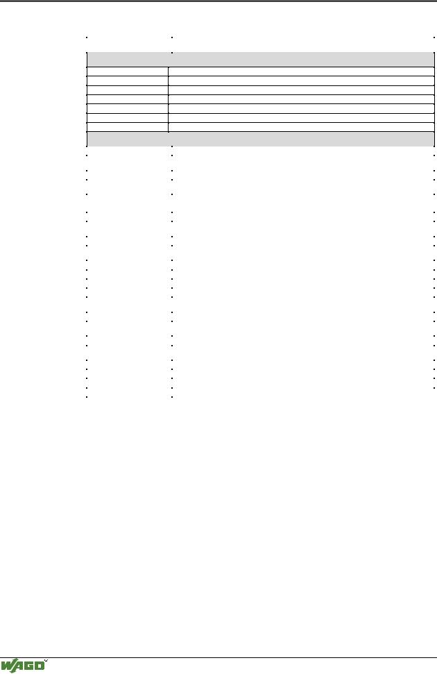
3.2.8.4Fault message via blink code from the I/O-LED
Fault argument |
Fault description |
|
|
Fault code 1: Hardware and Configuration fault
0EEPROM check sum fault / check sum fault in the parameter area of the flash memory
1Overflow of the internal buffer memory for the inline code
2Unknown data type
3Module type of the flash program memory could not be determined / is incorrect
4Fault when writing in the FLASH memory
5Fault when deleting the FLASH memory
6Changed I/O module configuration determined after AUTORESET
Fault code 2: Fault in programmed configuration
0 |
Incorrect table entry |
Fault code 3: Internal bus command fault |
|
|
|
0 |
No fault argument is put out. |
Fault code 4: Internal bus data fault |
|
|
|
0 |
Data fault on internal bus or |
|
Internal bus interruption on controller |
n* (n>0) |
Internal bus interrupted after I/O module n |
Fault code 5: Fault during register communication |
|
|
|
n* |
Internal bus fault during register communication after I/O module n |
Fault code 6: Fieldbus specific errors |
|
|
|
1 |
No answer from the BootP server |
2 |
ETHERNET controller not recognized |
3 |
Invalid MACID |
4 |
TCP/IP initialization error |
Fault code 7: I/O module is not supported |
|
|
|
n* |
I/O module at position n is not supported |
Fault code 8: not used |
|
|
|
0 |
Fault code 8 is not used. |
Fault code 9: CPU-TRAP error |
|
|
|
1 |
Illegal Opcode |
2 |
Stack overflow |
3 |
Stack underflow |
4 |
NMI |
* The number of blink pulses (n) indicates the position of the I/O module. I/O modules without data are not counted (i.e. supply modules without diagnostics).
Example for a fault message
Fault: The 13th I/O module has been removed.
4.The "I/O" LED starts the fault display with the first blink sequence (approx. 10 Hz).
5.The second blink phase (approx. 1 Hz) follows the first pause. The "I/O" LED blinks four times and thus signals the fault code 4 (internal bus data fault).
6.The third blink sequence follows the second pause. The "I/O ERR" LED
blinks twelve times. The fault argument 12 means that the internal bus is interrupted after the 12th I/O module.
Modular I/O System
ETHERNET TCP/IP

Fieldbus controller 750-842 • 91
LED Display
3.2.8.5Supply voltage status
There are two green LED’s in the controller supply section to display the supply voltage. The left LED (A) indicates the 24 V supply for the controller. The right hand LED (C) signals the supply to the field side, i.e. the power jumper contacts.
LED |
Meaning |
Trouble shooting |
|
|
|
A |
|
|
|
|
|
green |
Operating voltage for the system exists. |
|
OFF |
No operating voltage for the system. |
Check the supply voltage (24V and 0V). |
C |
|
|
|
|
|
green |
Operating voltage for the power jumper contacts |
|
|
exists. |
|
OFF |
No operating voltage for the the power jumper con- |
Check the supply voltage (24V and 0V). |
|
tacts. |
|
Modular I/O System
ETHERNET TCP/IP