Материал: m012900e
92 • Fieldbus controller 750-842
Fault behavior
3.2.9Fault behavior
3.2.9.1Fieldbus failure
A fieldbus failure is given i. e. when the master cuts-out or the bus cable is interrupted. A fault in the master can also lead to a fieldbus failure.
A fieldbus failure is indicated by illuminating the red "ERROR"-LED.
If the watchdog is activated, the watchdog-register is evaluated in the case of fault free communication.
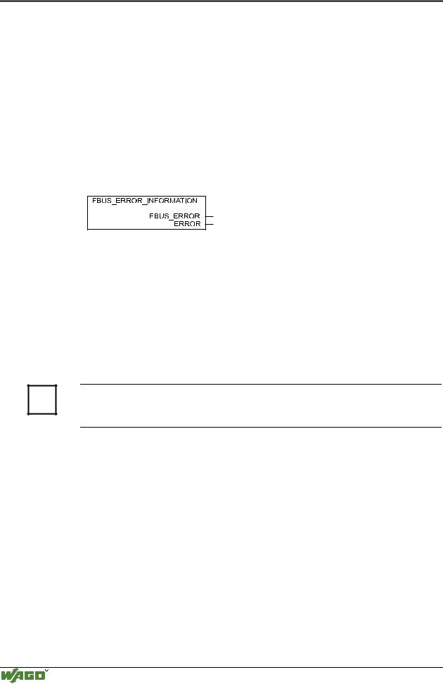
The evaluation of the watchdog register is made using the function block ’FBUS_ERROR_INFORMATION’in the control program. The internal bus remains in function and the process illustrations are retained. The control program can be further processed independently.
Fig. 3-37: Function block for determining a fieldbus failure |
g012926x |
||
’FBUS_ERROR’(BOOL) = FALSE = no fault |
|
||
|
= TRUE = fieldbus failure |
|
|
’ERROR’(WORD) |
= 0 |
= no fault |
|
|
= 1 |
= fieldbus failure |
|
The nodes can set to a safe status in the case of a fieldbus failure using these outputs and a corresponding control program.
More information
i For detailed information to the Watchdog register see Chaper 6.2.12 "Watchdog (Fieldbus failure)".
3.2.9.2Internal bus fault
An internal bus fault is created, for example, if an I/O module is removed. If this fault occurs during operation, the output modules behave in the same manner as an I/O module stop.
The "I/O" LED blinks red.
The controller generates a fault message (fault code and fault argument).
Once the internal bus fault is fixed, the controller starts up following power being cycled as during a normal start-up. The transfer of the process data is then resumed and the node outputs are correspondingly set.
Modular I/O System
ETHERNET TCP/IP

Fieldbus controller 750-842 • 93
Technical Data
3.2.10Technical Data
System data
Max. n. of nodes
Transmission medium
Buscoupler connection
Max. length of fieldbus segment
Baud rate
Protocols
Programming
IEC 61131-3-3
Approvals
limited by ETHERNET specification
Twisted Pair S-UTP 100 Ω cat. 5
RJ45
100 m between hub station and 750-342;
max. length of network limited by ETHERNET specification
10 Mbit/s
MODBUS/TCP, HTTP, BootP
WAGO-I-PRO
IL, LD, FBD, ST, FC
UL
Conformity marking
Technical Data
Max. n. of I/O modules
Input process image
Output process image
Input variables
Output variables
Configuration
Program memory
Data memory
Non-valatile memory
Cycle time
Max. n. of socket connections
Voltage supply
Input currentmax
Efficiency of the power supply
Internal current consumption
Total current for I/O modules
Isolation
Voltage via power jumper contactsmax
Current via power jumper contactsmax
Dimensions (mm) W x H x L
Weight
EMC Immunity to interference
EMC Emission of interference
E175199, UL508
Œ
64
max. 512 Byte
max. 512 Byte
max. 512 Byte
max. 512 Byte
via function blocks
128 Kbyte
64 Kbyte
8KByte
<3 ms for 1,000 statements/ 256 dig. I/O's
1 HTTP, 3 MODBUS/TCP, 2 PFC, 2 WAGO-I/O-PRO
DC 24 V (-15 % / + 20 %)
500 mA at 24 V
87 %
200 mA at 5 V
1800 mA at 5 V
500 V system/supply
DC 24 V (-15 % / + 20 %)
DC 10 A
51 x 65* x 100 (*from upper edge of DIN 35 rail)
approx. 195 g
acc. to EN 50082-2 (95)
acc. to EN 50081-2 (94)
Modular I/O System
ETHERNET TCP/IP

94 • I/O modules
4 I/O modules
All available bus modules in the WAGO-I/O-SYSTEM 750 are included in the following overview.
The following chapters contain a detailed description of each individual bus module and its variation.
Attention
The process data configuration of some bus modules or their variations are specific to the bus coupler used. For more detailed information please refer to the chapters "Process data architecture for MODBUS/TCP" in the process image description of the corresponding coupler/controller.
Modular I/O System
ETHERNET TCP/IP

I/O modules • 95
Review
4.1 I/O modules-Review
Digital Inputs |
start on page 98 |
|||||
Item- |
|
|
|
|
On |
|
No: |
|
Name |
|
page |
|
|
|
|
|
||||
|
|
|
|
|||
|
|
|
|
|
|
|
750-400 |
|
2 Channel Digital Input (filter 3.0 ms, DC 24 V) |
|
99 |
|
|
|
|
|
|
|
|
|
750-401 |
|
2 Channel Digital Input (filter 0.2 ms, DC 24 V) |
|
99 |
|
|
|
|
|
|
|
|
|
750-402 |
|
4 Channel Digital Input (filter 3.0 ms, DC 24 V) |
|
101 |
|
|
|
|
|
|
|
|
|
750-403 |
|
4 Channel Digital Input (filter 0.2 ms, DC 24 V) |
|
101 |
|
|
|
|
|
|
|
|
|
750-404 |
|
U/D Counter |
|
103 |
|
|
|
|
|
|
|
|
|
750-405 |
|
2 Channel Digital Input (AC 230 V) |
|
118 |
|
|
|
|
|
|
|
|
|
750-406 |
|
2 |
Channel Digital Input (AC 120 V) |
|
120 |
|
|
|
|
|
|
|
|
750-408 |
|
4 Channel Digital Input (filter 3.0 ms, DC 24 V) |
|
122 |
|
|
|
|
|
|
|
|
|
750-409 |
|
4 Channel Digital Input (filter 0.2 ms, DC 24 V) |
|
122 |
|
|
|
|
|
|
|
|
|
750-410 |
|
2 Channel Digital Input (filter 3.0 ms, DC 24 V) |
|
124 |
|
|
|
|
|
|
|
|
|
750-411 |
|
2 Channel Digital Input (filter 0.2 ms, DC 24 V) |
|
124 |
|
|
|
|
|
|
|
|
|
750-412 |
|
2 |
Channel Digital Input (filter 3.0 ms, DC 48 V) |
|
126 |
|
|
|
|
|
|
|
|
750-414 |
|
4 |
Channel Digital Input (filter 0.2 ms, DC 5 V) |
|
128 |
|
|
|
|
|
|
|
|
750-415 |
|
4 |
Channel Digital Input (filter 0.2 ms, AC/DC 24 V) |
|
130 |
|
|
|
|
|
|
|
|
Digital Outputs |
start on page 132 |
|||||
Item- |
|
|
|
|
On page |
|
No: |
|
Name |
|
|
|
|
|
|
|
|
|||
|
|
|
|
|
|
|
750-501 |
|
2 |
Channel Digital Output (0.5 A, DC 24 V) |
|
133 |
|
|
|
|
|
|
|
|
750-502 |
|
2 |
Channel Digital Output (2A, DC 24 V) |
|
133 |
|
|
|
|
|
|
|
|
750-504 |
|
4 |
Channel Digital Output (0.5 A, DC 24 V) |
|
135 |
|
|
|
|
|
|
|
|
750-506 |
|
2 |
Channel Digital Output (0.5 A, DC 24 V) diag. |
|
137 |
|
|
|
|
|
|
|
|
750-507 |
|
2 |
Channel Digital Output (2.0 A, DC 24 V) diag. |
|
139 |
|
|
|
|
|
|
|
|
750-509 |
|
2 |
Channel Solid State Relay (2 Outputs 0,3 A, AC 230 V) |
|
142 |
|
|
|
|
|
|
|
|
750-511 |
|
2 |
Channel Pulsewidth Output (0.1 A, DC 24 V) |
|
142 |
|
|
|
|
|
|
||
750-512 |
|
Digital Output Relay (2 normally open contact, non-floating, AC |
144 |
|
||
|
|
250 V) |
|
|
|
|
|
|
|
|
|
||
750-513 |
|
Digital Output Relay (2 normally open contacts, isolated outputs, 2.0 A, |
150 |
|
||
|
|
AC 250 V) |
|
|
|
|
|
|
|
|
|
||
|
|
|
|
|
||
750-514 |
|
Digital Output Relay (2 changeover contacts, isolated outputs, 0.5 A, |
153 |
|
||
|
|
AC 125 V) |
|
|
|
|
|
|
|
|
|
|
|
750-516 |
|
4 |
Channel Digital Output (0.5 A, DC 24 V) |
|
156 |
|
|
|
|
|
|
||
750-517 |
|
Digital Output Relay (2 changeover contacts, isolated outputs, 1.0 A, |
158 |
|
||
|
|
AC 230 V) |
|
|
|
|
|
|
|
|
|
|
|
750-519 |
|
4 |
Channel Digital Output (20 mA, DC 5 V) |
|
160 |
|
|
|
|
|
|
|
|
Modular I/O System
ETHERNET TCP/IP

96 • I/O modules
Review
Analog Inputs |
start on page 164 |
|||||
Item- |
|
|
|
|
On |
|
No: |
|
Name |
|
page |
|
|
|
|
|
||||
|
|
|
|
|||
|
|
|
|
|
|
|
750-452 |
|
2 |
Channel Analog Input (0-20mA, Diff.) |
|
165 |
|
|
|
|
|
|
|
|
750-454 |
|
2 |
Channel Analog Input (4-20mA, Diff.) |
|
165 |
|
|
|
|
|
|
|
|
750-456 |
|
2 |
Channel Analog Input (± 10 V, Diff.) |
|
169 |
|
750-461 |
|
2 |
Channel Input PT 100 (RTD) |
|
172 |
|
|
|
|
|
|
|
|
750-462 |
|
2 |
Channel Analog Input Thermocouple |
|
177 |
|
|
|
|
|
|
|
|
750-465 |
|
2 |
Channel Analog Input (0-20mA single-ended) |
|
186 |
|
|
|
|
|
|
|
|
750-466 |
|
2 |
Channel Analog Input (4-20mA single-ended) |
|
186 |
|
|
|
|
|
|
|
|
750-467 |
|
2 |
Channel Analog Input (0-10 V single-ended) |
|
190 |
|
|
|
|
|
|
|
|
750-468 |
|
4 |
Channel Analog Input (0-10 V single-ended) |
|
193 |
|
|
|
|
|
|
|
|
750-469 |
|
2 |
Channel Analog Input Thermocouple (detection of broken wire) |
196 |
|
|
|
|
|
|
|
|
|
750-472 |
|
2 |
Channel Analog Input (0-20mA single-ended) 16Bit |
|
203 |
|
|
|
|
|
|
|
|
750-474 |
|
2 |
Channel Analog Input (4-20mA single-ended) 16Bit |
|
203 |
|
|
|
|
|
|
|
|
750-476 |
|
2 |
Channel Analog Input (DC ± 10 Vsingle-ended) |
|
206 |
|
750-478 |
|
2 |
Channel Analog Input (DC 0-10 V single-ended) |
|
206 |
|
|
|
|
|
|
|
|
Analog Outputs |
start on page 209 |
|||||
Item- |
|
|
|
|
On |
|
No: |
|
Name |
|
page |
|
|
|
|
|
||||
|
|
|
|
|||
|
|
|
|
|
|
|
750-550 |
|
2 |
Channel Analog Output (DC 0-10 V) |
|
210 |
|
|
|
|
|
|
|
|
750-552 |
|
2 |
Channel Analog Output (0-20mA) |
|
214 |
|
|
|
|
|
|
|
|
750-554 |
|
2 |
Channel Analog Output (4-20mA) |
|
214 |
|
|
|
|
|
|
|
|
750-556 |
|
2 |
Channel Analog Output (DC ± 10 V) |
|
214 |
|
Modular I/O System
ETHERNET TCP/IP