Материал: m012900e
102 • I/O modules
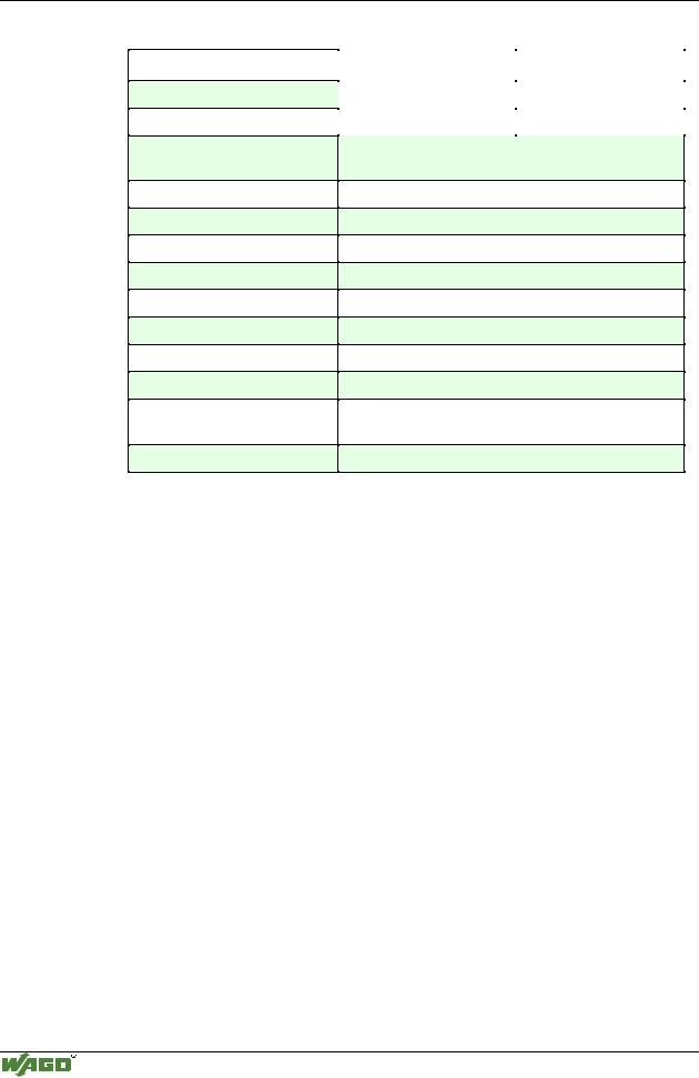
Digital Inputs 750-402, -403
Technical Data:
Item-No.:
Number of inputs
Input filter
Voltage via power jumper contacts
Signal voltage (0)
Signal voltage (1)
Input current (internal)
Input current (field side)
Isolation
Internal bit width
Configuration
Operating temperature
Wire connection
Dimensions (mm) WxHxL
750-402 |
|
750-403 |
|
4 |
|
|
|
|
3 ms |
|
0.2 ms |
|
|
|
DC 24V (-15% / +20%)
DC -3 V...+5 V (std. EN 61131 Type 1)
DC 15 V...30 V (std. EN 61131 Type 1)
5 mA max.
5 mA typ.
500 V System/power supply
4
no address or configuration adjustment
0°C....+55°C
CAGE CLAMP ; 0.08 mm2 - 2.5 mm2, AWG 28 – 14, 8 – 9 mm Stripped length
12 x 64* x 100 (*from upper edge of carrier rail)
Modular I/O System
ETHERNET TCP/IP
I/O modules • 103
Counter modules 750-404, /000-XXX
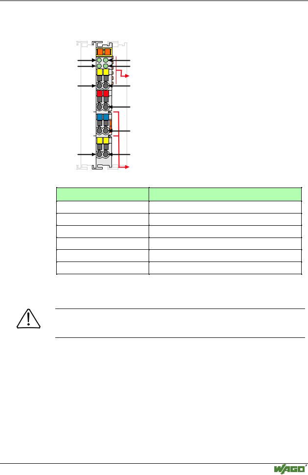
4.2.1.1.3 Counter modules 750-404/000-XXX Up Down Counter100kHz 750-404
Status |
13 |
14 |
A |
|
|
U/D |
|
|
|
C |
|
DO 1 |
B |
|
|
D |
|
|
U/D CLK |
|
U/D |
|
|
|
+ |
+ |
|
- |
- |
|
A1 |
A2 |
DO 1 |
|
|
|
750-404 |
|
Status
CLOCK
DO 2
Data contacts
CLOCK
24V
0V
DO 2
Power jumper contacts
I/O modules and variations
Item-No.:
750-404
750-404/000-001 (s. page 107)
750-404/000-002 (s. page 108)
750-404/000-003 (s. page 109)
750-404/000-004 (s. page 114)
750-404/000-005 (s. page 116 )
Name:
Up/Down Counter
Counter with enable input
Peak Time Counter
Frequency Counter Module (0.1-10 kHz)
Up/Down Counter (switching outputs)
2 Channel Up Counter 16Bit
Technical description
Attention
The description that is in the I/O ring binder data pages (888-530/013-600 dated 7/96) is not correct. The bottom contacts are additional outputs.
The described configuration is counter with up/down input.
The following description is preliminary and is applicable to the factory configuration.
The counter module can operate with all WAGO-I/O-SYSTEM bus-couplers (except for the economy type).
Modular I/O System
ETHERNET TCP/IP
104 • I/O modules
Counter modules 750-404, /000-XXX
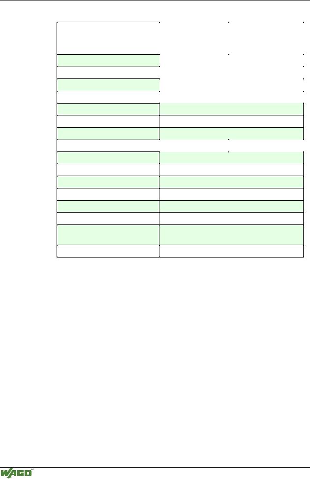
Technical Data:
Item-No.:
Number of outputs
Number of counters
Output current
Input current (internal)
Voltage via power jumper contacts
Signal voltage (0)
Signal voltage (1)
Switching rate
Input current (field side)
Counter size
Isolation
Internal bit width
Configuration
Operating temperature
Wire connection
Dimensions (mm) WxHxL
750-404, |
|
750-404/000-002 |
750-404/000-001, |
|
|
750-404/000-004 |
|
|
|
2 |
|
|
|
|
|
1 |
|
|
|
|
|
0.5 A |
|
|
|
|
|
70 mA |
|
|
|
|
DC 24 V (-15 % / + 20 %)
DC -3 V ... +5 V
DC + 15 V ... 30 V
100 kHz max |
10kHz max |
|
|
5 mA typ.
32 Bit Data
500V System/power supply
32 Bit Data, 8 Bit Control/Status
none, or via software with the consent of WAGO
0 °C ... + 55 °C
CAGE CLAMP ; 0.08 mm2 - 2.5 mm2, AWG 28 – 14, 8 – 9 mm Stripped length
12 x 64* x 100, (*from upper edge of carrier rail)
Modular I/O System
ETHERNET TCP/IP
I/O modules • 105
Counter modules 750-404, /000-XXX
Organization of the input and output data:
The counter begins processing with pulses at the CLOCK input. The changes from 0 V to 24 V are counted. (The leading edge of each pulse.)
The counter counts up, if the input U/D is set at 24 V. With an open circuit input or 0 V the counter counts backwards (down).
The two bottom contacts are 24V outputs. These outputs are activated through bits in the control byte.
The high states of the input and output channels are each indicated by a LED.
Attention
For the process data configuration of these bus modules please refer to chapter "Process data architecture for MODBUS/TCP" in the process image description of the corresponding coupler/controller.
The control byte has the following bits::
Bit |
7 |
Bit |
6 |
Bit 5 |
Bit 4 |
Bit 3 |
Bit 2 |
Bit |
1 |
Bit 0 |
|
|
|
|
|
|
|
|
|
|
|
0 |
|
x |
|
Set |
Block |
Output |
Output |
x |
|
X |
|
|
|
|
Counter |
Counter |
value at |
value at |
|
|
|
|
|
|
|
|
|
output O2 |
output O1 |
|
|
|
|
|
|
|
|
|
|
|
|
|
|
The status byte has the following bits:
Bit |
7 |
Bit |
6 |
Bit 5 |
Bit 4 |
Bit 3 |
Bit 2 |
Bit 1 |
Bit 0 |
|
|
|
|
|
|
|
|
|
|
x |
|
x |
|
Counter is |
Counter is |
State of |
State of |
24 V signal at |
actual si- |
|
|
|
|
set |
blocked |
signal at |
signal at |
input U/D, |
gnal at |
|
|
|
|
|
|
output O1 |
output O1 |
counter |
input |
|
|
|
|
|
|
|
|
counts up |
CLOCK |
|
|
|
|
|
|
|
|
|
|
With the control and status byte the following tasks are possible:
Setting the counter:
Set Bit 5 in the control byte to "1". The desired counter value with the 32 bit value is loaded into output bytes 0-3. As long as the bits are set, the counter can stop and information is stored. The ensuing data of the counter will be conveyed to the status byte.
Blocking the counter:
Bit 4 is set into the control byte, then the count process is suppressed. Bit 4 in the status byte communicates the suppression of the counter.
Setting the outputs:
Bits 2 and 3 set the additional two outputs of the counter module.
The result of the counter is in binary. The following tasks can be handled with the control byte and the status byte:
Modular I/O System
ETHERNET TCP/IP
106 • I/O modules
Counter modules 750-404, /000-XXX
An example:
Setting counter to a value of 100 and counting up
First of all the counter reading is set to 100 by "Setting counter", i. e. to the hexadecimal value: 0x64.
1.Enter the counter reading in the output data.
The data bytes D0 to D3 of the output data then read as follows:
D3 |
D2 |
D1 |
D0 |
0x00 |
0x00 |
0x00 |
0x64 |
2.Validate the counter reading in the control byte with bit 5 (setting counter) to have it adopted as an output value. The control byte has the following bits:
Bit |
7 |
Bit 6 |
Bit |
5 |
Bit 4 |
Bit 3 |
Bit 2 |
Bit 1 |
Bit 0 |
0 |
|
X |
1 |
|
X |
X |
X |
X |
X |
3.Wait for the feedback from the counter module in the status byte, bit 5 (counter set). The status byte has the following bits:
Bit 7 |
Bit 6 |
Bit |
5 |
Bit 4 |
Bit 3 |
Bit 2 |
Bit 1 |
Bit 0 |
X |
X |
1 |
|
X |
X |
X |
X |
X |
4.Set bit 5 (setting counter) in the control byte in order to finish the Handshake. The bits in the control byte read as follows:
Bit |
7 |
Bit 6 |
Bit |
5 |
Bit 4 |
Bit 3 |
Bit 2 |
Bit 1 |
Bit 0 |
0 |
|
X |
0 |
|
X |
X |
X |
X |
X |
5.The set counter reading then appears in the input data with the following data bytes D0 to D3:
D3 |
D2 |
D1 |
D0 |
0x00 |
0x00 |
0x00 |
0x64 |
Counter counting up:
Attention
For counting up, 24 V must be applied to input U/D.
6.Wait for the first and further count pulses.
During counting, the data bytes D0 to D3 of the input data appear as follows:
D3 |
D2 |
D1 |
D0 |
Remark |
|
0x00 |
0x00 |
0x00 |
0x64 |
no count pulse received |
|
0x00 |
0x00 |
0x00 |
0x65 |
1st count pulse received |
|
0x00 |
0x00 |
0x00 |
0x66 |
2nd count pulse received |
|
........ |
........ |
........ |
........ |
|
|
0xFF |
0xFF |
0xFF |
0xFF |
Max. counter reading reached |
|
0x00 |
0x00 |
0x00 |
0x00 |
the next count pulse causes a number overflow |
|
0x00 |
0x00 |
0x00 |
0x01 |
One further count pulse received |
|
........ |
........ |
........ |
........ |
|
|
|
|
|
|
|
|
Attention
"X" is used if the value at this position is without any significance.
Modular I/O System
ETHERNET TCP/IP